
User Manual for Powe Burner Diamond Series

6
L-C2-333
REV 3 - 1601181405
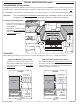
SUBSTRATE
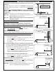
When adding any substrate to the enclosure front wall (including tiles, stone, etc.), consider the following:
Substrate Behind Control Panel
Substrate Alongside Control Panel
C
C
Flush
(Control panel)
(Countertop)
(Countertop)
(Control panel)
Substrate
(includes tiles,
etc. at front of
enclosure)
Countertop
overhang
(if applicable)
Flush
Power burner
liner
Substrate
(includes tiles,
etc. at front of
enclosure)
1
/4"
Clearance
Any additional substrate alongside the control panel
does not need to be considered in Dim. C (see previous
page), however a
1
/4" clearance on each side (same as
overhang) and below is required.
Substrate
+
countertop "front to back" cutout
must equate to Dim. C (see previous page)
when the substrate sits fl ush behind the
control panel.
Fig. 6-2 Fig. 6-3
Countertop
overhang
(if applicable)
TOP VIEW TOP VIEW
1
/4"
Clearance
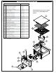
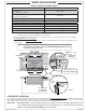
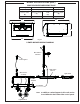
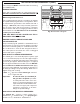
RECOMMENDED OFFSET INSTALL
It is highly recommended to build the enclosure for the power burner 6"-12" LOWER than your countertop (see Fig. 6-1).
This will ensure a safer environment when using tall cooking pots like a turkey fryer, which can hold 40 lbs of hot oil.
Consult Table 1 for power burner cut out dimensions. See Fig. 6-1 below for countertop offset installation information.
Important: The surrounding non-combustible walls must have a minimum clearance of 2" beyond
the power burner hangers to allow for proper installation, airfl ow, and ventilation.
If using an insulating liner:
• Consult liner instructions for
enclosure cut-out dimensions
and installation.
• Ensure the 2" clearance for the
surrounding non-combustible
walls is calculated beyond the
insulating liner hangers.
Power burner
liner
2" min.
6-12"
Fig. 6-1
MODEL SPECIFICATIONS (cont.)