
User Manual for Powe Burner Diamond Series

8
L-C2-333
REV 3 - 1601181405
1. The power burner and surrounding area MUST
remain clear of fl ammable substances such as
gasoline, yard debris, wood, etc.
2. The airfl ow through the vent space located below
the control panel must remain unobstructed.
3. When using propane gas:
a. The required ventilation openings in the
enclosure must be clear of debris. See the
PROPANE SAFETY INFORMATION section.
b. The propane cylinder, regulator, and rubber
hose must be in a location not subject to
temperature above 125° F (51° C).
4. The fl ames on each burner burn evenly along the
entire burner with a steady fl ame (mostly blue). If
burner fl ames are not normal, check and clean
the orifi ce and burner/venturi tubes for insects
and insect nests. A clogged tube can lead to a fi re
beneath the unit. A proper fl ame pattern will ensure
safe operation and optimal performance. Adjust
the air shutter as needed (see AIR SHUTTER
ADJUSTMENT).
5. The in-line gas valve or gas cylinder valve must
always be shut OFF when the unit is not in use.
6. Do not operate the burner with the cover in place.
7. Whenever reconnecting any wires, apply a small
amount of dielectric grease to the male connector,
then make the connection. This will ensure
conductivity and prevent moisture from affecting
the contact.
WARNING: NEVER cover more than 75% of the cooking surface with griddles or pans. Overheating will occur, and
burners will not perform properly when combustion heat is trapped below the cooking surface.
CAUTION: NEVER spray water on a hot gas unit.
ELECTRICAL CONNECTIONS
A 120VAC (15 AMP minimum) Ground Fault Circuit
Interrupter (GFCI) GROUNDED 3-wire receptacle
(not included) is required within the vicinity of the unit
to provide power to the unit.
• Observe all local codes.
• Verify proper polarity of the receptacle.
• If an extension cord is used, ensure it is a 3-wire
GROUNDED cord that is rated for the power of
the equipment, and is approved for outdoor
use with a W-A marking. DO NOT use 2-prong
adapters.
• DO NOT TAMPER WITH THE EXTENSION CORD
OR THE UNIT POWER-SUPPLY CORD.
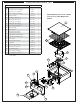
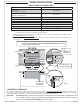
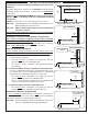
LIGHT SWITCH
The light switch is push button operated, and is
located on the right side of the control panel (see
Fig. 8-1). It controls the power to the lighted knobs
and igniters. It allows the power to be turned on or
off for safety and convenience. The switch will need
to be turned on prior to each use, and turned off
after each use.
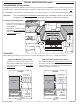
The unit serial identifi cation number is located on the underside of the drip tray handle. It
is recommended that the drip tray fi rst be removed and cleaned / emptied of its contents,
then turned over to view. The unit rating label is located on the inside of the control panel.
Light
switch
Fig. 8-1
MAINTENANCE AND SAFETY INFORMATON