
Installation and Operating Instructions


5
WARNING
The power burner must be installed in masonry
or other type of fi reproof surround. The unit is not
insulated and therefore must be installed or placed
with 18
"
(45.7 cm) of side and back clearance from
unprotected combustible materials such as wood,
plastic, or stucco with wood framing.
Do not install this unit under unprotected fl ammable
surfaces. Do not install or use this appliance inside a
building, garage, or any other enclosed area. It must
not be used in or on recreational vehicles or boats.
This is a slide-in unit designed to fit into open-front
enclosures. Control panel of the unit is removable for gas
hookup, servicing and burner adjustment. Control panel
must remain removable after you install the unit.
Important: The hanger requires 2" (5.1 cm) of
countertop on each side and back to
support the unit.
Note: We recommend you build the enclosure for
the power burner 6"-12" (15.2 cm- 30.5 cm)
LOWER than your countertop (see Fig. 5-2).
This will ensure a safer environment when using
tall cooking pots like the turkey fryer, which can
hold 40 lbs of hot oil.
PLANNING FOR INSTALLATION OF YOUR POWER BURNER
Note: This unit should be installed so that it can be
removed at a later date if factory service is
required. Any protrusion into the power burner
enclosure may prevent the unit from sliding
into place (see GAS SUPPLY PLUMBING
REQUIREMENTS).
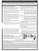
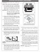
ENSURING PROPER COMBUSTION AIR AND
COOLING AIR FLOW
You must maintain proper air fl ow for your Fire Magic power
burner to perform as it was designed (Fig. 5-1). If airfl ow
is blocked, overheating and poor combustion will result.
Make sure not to block the 1" (2.5 cm) front air inlet along
the bottom of the control panel or more than 75% of the
support grid surface with pans or griddles.
Note: The 1" (2.5 cm) front air space allows access
to the drip tray.
EXHAUST REMOVAL
If installed under a patio roof, the cooking grid area should
be fully covered by a chimney and exhaust hood. An exhaust
fan with a rating of up to 1,000 CFM (472 liters per second)
may be necessary to effi ciently remove smoke and other
cooking by-products from the covered area. Installation in
fully enclosed patio areas is not recommended.
Fig. 5-1 - Ventilation Diagram
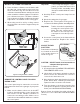
GAS SUPPLY PLUMBING REQUIREMENTS
Rigid
1
/
2
" (1.3 cm) or
3
/
4
" (.75 cm) black steel pipe, or local
code approved pipe for temperatures up to 800°F (427°C),
is required to conduct the gas supply into the enclosure
opening for connection to the unit. Do not use a rubber
hose within the enclosure for the power burner. Apply
only joint compounds that are resistant to all gasses on
all male pipe fi ttings. Make sure to tighten every joint
securely.
The gas supply pipe should terminate below the power
burner so fi nal connection can be made with an approved
fl ex connector.
Install the gas line stub
at least 1
1
/
2
" (3.8 cm)
away from the side
walls and 1
" (2.54 cm)
from the back wall,
but within 5
" (12.7
cm) of the back wall,
as illustrated by the
shaded area in Fig.
5-2.
Note: An external
valve (with
a removable
key) in the gas line is necessary for safety when
your power burner is not in use. It also provides
for convenient maintenance.
You will need a C.S.A. approved stainless steel flex
connector to bring the gas supply from the gas line stub to
the regulator. A
1
/
2
" (1.27 cm) x 36" (91.4 cm) or 24" (61
cm) fl ex connector with
1
/
2
" (1.27 cm) fl are to
1
/
2
" (1.27 cm)
pipe adapter on one end, and a
1
/
2
" (1.27 cm) fl are female
fi tting on the other end is suitable for most installations.
CAUTION: Use only stainless steel fl ex connectors
that are C.S.A. listed. A rubber or plastic
connector will rupture or leak, resulting in
an explosion or serious injury if used inside
the power burner enclosure.
Important: See page 7 for the proper venting of the
enclosure.
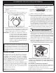
GAS SUPPLY AND MANIFOLD PRESSURES
For natural gas - Normal 7" (17.8 cm) water column (w.c.),
Minimum 3
1
/
2
" (8.9 cm) w.c., Maximum 10
1
/
2
" (26.7 cm) w.c.
For propane gas Normal 11" (27.9 cm) (w.c.), Minimum 8"
(20.3 cm) (w.c.), Maximum 13" (33 cm).
GAS SUPPLY PRESSURE TESTING
This appliance and its individual shutoff valves must be
disconnected from the gas supply piping system when
testing the system at pressures in excess of
1
/
2
psig (3.5
kpa).
This appliance must be isolated from the gas supply piping
system by closing its individual manual shutoff valves during
any pressure testing of the gas supply system at pressures
up to and including
1
/
2
psig (3.5 kpa).
GAS PLUMBING REQUIREMENTS FOR YOUR SLIDE-IN POWER BURNER
19”
1”
18 3/4”
1 1/2”
1 1/2”
4”
12”
12”
Fig. 5-2 - Gas stub diagram
Optional 6 - 12" (15.3 - 30 cm) Drop
WHERE TO INSTALL THE POWER BURNER
IMPORTANT: THIS POWER BURNER IS FOR
OUTDOOR USE ONLY.
REV 7 - 0907160842
L-C2-06209