
Installation and Operating Instructions


8
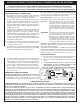
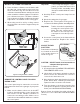
Fig. 8-3 Sliding into place
Perform the following checks before installing your
power burner:
CHECK FUEL ORIFICES FOR PROPER SIZE
1. Your Fire Magic power burner is equipped with
fuel orifi ces for natural gas, unless otherwise
indicated. To change the gas type, you must install
different orifi ces to avoid hazardous overheating.
(Refer to Table 1 for the proper orifi ce size)
IMPORTANT: When converting orifi ces for different
gas type, the regulator must also
be converted for the new gas type.
Reference the REMOVE THE
CONTROL PANEL and CONVERTING
THE REGULATOR sections.
2. Remove the cooking grid. Grip the flame
collimator and remove it by compressing the ring
slightly front to back and lifting the compressed
end upward. (Reference Fig. 7-1.)
3. Check the orifi ce size by lifting the burner up and
out of the locator hole and pulling it away from
the orifi ces. The orifi ce size is stamped on the
orifi ce face. Be sure not to lose the air shutter or
air shutter spring which may become detached
when the burner is removed.
POSITION THE BURNER FOR OPERATION
1. After checking orifi ce size install the air shutter
spring and the air shutter over the orifi ce holder
fi tting, between the burner and the heat shield,
in the order and position shown in Fig. 8-2.
2. Carefully place the burner stud back in the locator
hole so that the brass orifi ce and orifi ce holder
fi ttings project into the burner air venturi. When
the burner stud fi ts in the locator hole the orifi ce
is in alignment.
CONNECT THE GAS SUPPLY TO THE POWER
BURNER
1. Make sure that your gas supply is turned OFF.
Then connect the
1
/
2
" pipe adapter fitting
supplied with the stainless steel fl ex connector
to the gas supply stub. Use pipe joint compound
that is resistant to all gasses on the male pipe
fi tting and tighten securely. Do not use pipe joint
compound on fl are fi ttings.
INSTALLING YOUR FIRE MAGIC POWER BURNER
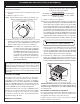
Fig. 8-4 Connecting the gas supply
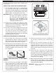
Flame collimator / wok ring
Fig. 8-2
Burner air venturi
Orifi ce
2. Slide your power burner into place, making sure
not to pinch or kink the gas connector (Fig.
8-3).
3. Bring the fl ex connector along the left side of
the power burner to the front of the unit and the
regulator inlet fl are fi tting. Use the connector
support bracket to hold the fl ex connector up
away from the drip tray and keep front vent clear
(Fig.
8-4).
4. Connect the fl ex connector to the fl are fi tting
on the regulator. Support the regulator inlet
fi tting with a wrench to avoid applying excessive
torque to the manifold assembly while tightening
this connection securely. DO NOT use pipe
compound on fl are fi ttings.
5. Make sure the power burner valves are in the OFF
position. Turn the gas supply on. Then carefully
check all gas connections for leaks with a brush and
soapy water before lighting.
WARNING: Never use a match or open fl ame to
test for leaks.