
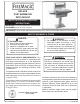
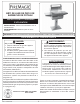
Installation and Operating Instructions

7
Important: An external valve (with a removable
key) in the gas line is necessary for
safety when the barbecue is not in
use. It also provides for convenient
maintenance.
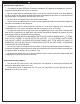
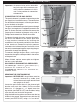
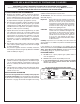
CONNECTING TO THE GAS SUPPLY
This post barbecue is capable of connecting to the
gas supply in a few different ways. The connection
can be made inside the post, under the post base,
or out the back of the post.
The gas must be hooked up so that it passes through
the timer (and regulator, if equipped) located in the
post. To access the timer, unscrew and remove the
access plate in the back of the post using a No. 3
Phillips-head screwdriver. Retain the screws.
To connect through the post, remove the knock-
out disk at the bottom of the access plate with
a large standard screwdriver by inserting the
screwdriver into the notch provided in the center
of the knock-out. Remove the plastic grommet
fastened to the inside of the post and insert it into
the newly created opening prior to passing the gas
connection through the opening.
To connect through the post base, run the gas
connection through the hole provided in the center
of the post base.
When fi nished, replace access plate and tighten
the four screws provided.
GAS SUPPLY AND MANIFOLD PRESSURES
For natural gas - Normal 7" water column (w.c.),
minimum 5" w.c., maximum 10
1
/
2
" w.c.
For propane gas - Normal 11" w.c., minimum 8" w.c.,
maximum 13" w.c.
Access plate
Knock-out
Grommet (installed)
Fig. 7-4
Fig. 7-3
Post (access panel removed)
Flex connector
through hole in
base
Back of timer valve
Grommet
attached with
tie
Location of
regulator if
equipped
(for natural gas
only)
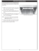
Fig. 7-2
Adjustable
Nut
Tension
Bolt
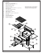
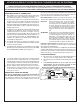
INSTALLATION (Cont.)
SECURING THE POST BARBECUE
Important: BEFORE USE, the grill base must be
securely fastened to a stable, level
surface to ensure the grill remains fi xed
and upright at all times.
Locate the patio mount base in the planned grill
location and mark the 4 holes. Drill the marked
holes to a
1
/
2
" diameter x 1
1
/
2
" depth. Insert the
lag shields (see PARTS LIST) into the holes, being
sure that they are fl ush with the ground.
Align the holes on the patio mount base over the lag
shields in the ground. Secure the base with the lag
screws (see PARTS LIST) using a
7
/
16
" nut driver.