CHIMNEY BOX VENTILATION HOOD HC24DTXB2, HC30DTXB2 & HC36DTXB2 models HOTTE DE VENTILATION MURALE DÉCORATIVE Modèles HC24DTXB2, HC30DTXB2 & HC36DTXB2 INSTALLATION GUIDE / USER GUIDE GUIDE D’INSTALLATION / GUIDE D’UTILISATION US CA
English Page 1 – 22 Français Page 25 – 46
CONTENTS EN Introduction 3 Safety and warnings 4 Installation instructions 6 Operating instructions 18 Cleaning and maintenance 19 Parts and accessories 21 Service and Warranty 22 IMPORTANT! SAVE THESE INSTRUCTIONS The models shown in this user guide may not be available in all markets and are subject to change at any time. For current details about model and specification availability in your country, go to our website fisherpaykel.com or contact your local Fisher & Paykel dealer.
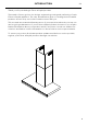
INTRODUCTION EN Thank you for purchasing a Fisher & Paykel product. Thousands of hours go into the design, engineering, testing and perfecting of each Fisher & Paykel appliance. The care and attention given to creating these beautiful products doesn’t stop once it has found its home with you.
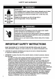
SAFETY AND WARNINGS ● ● ● ● ● ● ● EN –– When cutting or drilling into wall or ceiling, do not damage electrical wiring and other hidden utilities. –– Ducted fans must always be vented to the outdoors. –– This unit must be grounded. CAUTION: To reduce risk of fire and to properly exhaust air, be sure to duct air outside — Do not vent exhaust air into spaces within walls or ceilings or into attics, crawl spaces, or garages. WARNING: To reduce the risk of fire, use only metal ductwork.
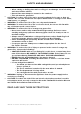
INSTALLATION INSTRUCTIONS Contents of packaging CH MNEY BOX VENTILAT ON HOOD HOTTE DE VENTILATION MURALE DÉCORAT VE US CA 6 Ventilation hood (1) Installation instructions User guide manual (1) Chimney (1) Upper chimney (1) Upper chimney bracket (1) Chimney bracket (1) Power connection box (1) 6” (152 mm) diameter Ducting adapter with back draft damper (1) 1 3/16” (30 mm) Expansion plug (10)
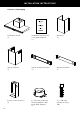
INSTALLATION INSTRUCTIONS 1 3/16” (30 mm) Self tapping screw (10) 3/8” (10 mm) Self tapping screw (4) EN 3/8” (10 mm) Screw (2) 1 3/4” (44 mm) Drywall expansion plug (8) 7
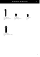
INSTALLATION INSTRUCTIONS Product dimensions Øj UL power connection box i h C g f A max A min D E B l k Please read the entire instructions before installing the ventilation hood.
INSTALLATION INSTRUCTIONS EN HC24DTXB2 HC30DTXB2 HC36DTXB2 inches (mm) inches (mm) inches (mm) A Min overall height of product 23 3/4” (603) 23 3/4” (603) 23 3/4” (603) A Max overall height of product 41 1/16” (1043) 41 1/16” (1043) 41 1/16” (1043) B Overall width of product 23 9/16” (598) 29 3/4” (755) 35 3/8” (898) C Overall depth of product 19 11/16” (500) 19 11/16” (500) 19 11/16” (500) D Height of product 2 9/16” (65) 2 9/16” (65) 2 9/16” (65) E Height of stainless steel fac
INSTALLATION INSTRUCTIONS Height of ventilation hood M N INSTALLATION DIMENSIONS M Installation height Ducted Recirculation N Height top of cooking surface inches (mm) min. 24 11/16” (627) – max. 43 1/16” (1034) min. 26 7/8” (682) – max. 43 1/16” (1034) min. 26” (660) – max. recommended 36” (915) to base of product This ventilation hood must be installed no lower than the minimum height indicated in the table above.
INSTALLATION INSTRUCTIONS EN WARNING! To reduce the risk of fire, use only metal ductwork. Do not use flexible plastic ducting CAUTION! To reduce risk of fire and to properly exhaust air, be sure to duct air outside — do not vent exhaust air into spaces within walls or ceilings or into attics, crawl spaces, or garages. Venting options Attention should be given to ensure that any applicable regulations concerning the discharge of exhaust air are fulfilled.
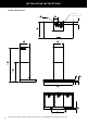
INSTALLATION INSTRUCTIONS u EN Upper chimney bracket attachment points v s Chimney bracket attachment points Upper ventilation hood attachment point q t Lower ventilation hood attachment point r p o Fig.
INSTALLATION INSTRUCTIONS EN 4 Wall mounting ● ● ● ● Remove the filters — pull the relative catch and tilt the filter downwards until it disengages from the supports. Hang the ventilation hood off the upper ventilation hood mounting screws with 1/16” (2 mm) gap. Hang off the keyhole attachment points on the back of the ventilation hood then tighten the screws. Attach the lower ventilation hood mounting screws to fix the ventilation hood to the wall. Refit the filters.
INSTALLATION INSTRUCTIONS WARNING! Electrical wiring must be done by qualified person(s) in accordance with all applicable codes and standards and the unit must be grounded.
CLEANING AND MAINTENANCE EN WARNING! Unplug or disconnect the appliance from the power supply before servicing or cleaning. IMPORTANT! ● ● Never use abrasive or oil based cleaners. Wear gloves to protect against sharp edges. Maintenance The ventilation hood should be cleaned regularly using a mild, liquid detergent and a clean soft cloth to avoid a build-up of grease occurring. Avoid the use of corrosive chemicals, abrasive cleaning products, hard brushes and steel wool pads.
PARTS AND ACCESSORIES ITEM REFERENCE NUMBER LED bulb 792579 Aluminum filter 792558 Recirculation carbon filter x2 791772 Recirculation diverter 792580 EN 21
SERVICE AND WARRANTY For details of your manufacturer’s warranty and contacts for servicing, please refer to your separate service and warranty book provided with your range hood. Complete and keep for safe reference: Model Serial No.
23
TABLE DES MATIÈRES Introduction FR 27 Consignes de sécurité et mises en garde 28 Instructions d’installation 30 Instructions d’utilisation 42 Nettoyage et entretien 43 Pièces et accessoires 45 Service et garantie 46 IMPORTANT! CONSERVEZ CES INSTRUCTIONS Les modèles illustrés dans ce guide d’utilisation peuvent ne pas être disponibles dans tous les pays et sont sujets à modifications sans préavis.
INTRODUCTION FR Nous vous remercions d’avoir acheté ce produit Fisher & Paykel. Plusieurs milliers d’heures sont consacrées à la conception, l’ingénierie, la mise à l’essai et le perfectionnement de chaque appareil Fisher & Paykel. L’attention et le soin portés à la création de ces superbes produits se poursuivent même après leur livraison à votre domicile.
CONSIGNES DE SÉCURITÉ ET MISES EN GARDE ● ● ● ● ● ● ● FR –– Pour éviter le refoulement d’air, une quantité d’air suffisante est nécessaire pour assurer une bonne combustion et l’évacuation des gaz à travers le carneau (cheminée) de l’appareil.
INSTRUCTIONS D’INSTALLATION Contenu de l’emballage CHIMNEY BOX VENT LAT ON HOOD HOTTE DE VENT LAT ON MURALE DÉCORATIVE US CA 30 Hotte de ventilation (1) Instructions d’installation Guide d’utilisation (1) Cheminée (1) Cheminée supérieure (1) Support de cheminée supérieure (1) Support de cheminée (1) Boîtier de raccordement d’alimentation (1) Adaptateur de conduit de 6 po (152 mm) de diamètre avec clapet antirefoulement d’air (1) Cheville expansible de 1 3/16 po (30 mm) (10)
INSTRUCTIONS D’INSTALLATION Vis autotaraudeuses de 1 3/16 po (30 mm) (10) Vis autotaraudeuses de 3/8 po (10 mm) (4) FR Vis de 3/8 po (10 mm) (2) Chevilles expansibles pour cloison sèche de 1 3/4 po (44 mm) (8) 31
INSTRUCTIONS D’INSTALLATION Dimensions du produit Øj Boîtier de raccordement d’alimentation UL i h C g f A max. A min. D E B l k Veuillez lire toutes les instructions avant d’installer la hotte de ventilation.
INSTRUCTIONS D’INSTALLATION FR HC24DTXB2 HC30DTXB2 HC36DTXB2 DIMENSIONS DU PRODUIT pouces (mm) pouces (mm) pouces (mm) A Hauteur hors tout min. du produit 23 3/4 po (603) 23 3/4 po (603) 23 3/4 po (603) A Hauteur hors tout max.
INSTRUCTIONS D’INSTALLATION Hauteur de la hotte de ventilation M N DIMENSIONS D’INSTALLATION pouces (mm) M Hauteur d’installation Avec conduit Avec recirculation N Hauteur du dessus de la surface min. 24 11/16 po (627) – max. 43 1/16 po (1 034) min. 26 7/8 po (682) – max. 43 1/16 po (1 034) min. 26 po (660) – max. recommandé 36 po (915) de cuisson à la base du produit La hotte de ventilation doit être installée en respectant le dégagement minimal et maximal indiqués dans le tableau ci-dessus.
INSTRUCTIONS D’INSTALLATION FR MISE EN GARDE! Pour réduire les risques d’incendie, utilisez uniquement des conduits en métal. N’utilisez pas de conduits en plastique flexible. ATTENTION! Pour réduire les risques d’incendie et évacuer l’air adéquatement, assurez-vous d’évacuer l’air vers l’extérieur – n’évacuez pas l’air dans les murs, plafonds, greniers, vides sanitaires ou garages.
INSTRUCTIONS D’INSTALLATION u FR Points de fixation du support de cheminée supérieure v s q Points de fixation du support de cheminée Points de fixation supérieurs de la hotte de ventilation t Points de fixation inférieurs de la hotte de ventilation r p o Fig.
INSTRUCTIONS D’INSTALLATION FR 4 Montage au mur ● ● ● ● Retirez les filtres – tirez sur le loquet afin d’incliner le filtre vers le bas jusqu’à ce qu’il se désengage des supports. Suspendez la hotte de ventilation sur les vis de montage supérieures avec un espace de 1/16 po (2 mm). Suspendez-la à l’aide des points de fixation avec encoche en trou de serrure situés à l’arrière, puis serrez les vis. Installez les vis de montage inférieures de la hotte de ventilation pour la fixer au mur.
INSTRUCTIONS D’INSTALLATION MISE EN GARDE! Le câblage électrique doit être réalisé par une ou plusieurs personne(s) qualifiée(s), en conformité avec tous les codes et toutes les normes applicables, en veillant à ce que l’appareil soit mis à la terre.
NETTOYAGE ET ENTRETIEN FR MISE EN GARDE! Débranchez ou déconnectez l’appareil de l’alimentation électrique avant de procéder à l’entretien ou au nettoyage. IMPORTANT! ● ● N’utilisez jamais de nettoyants abrasifs ou à base d’huile. Portez des gants pour vous protéger des rebords tranchants. Entretien La hotte de ventilation doit être nettoyée régulièrement à l’aide d’un détergent liquide doux et d’un chiffon doux et propre pour éviter l’accumulation de dépôts de graisse.
PIÈCES ET ACCESSOIRES FR ARTICLE NUMÉRO DE RÉFÉRENCE Ampoule LED 792579 Filtre en aluminium 792558 Filtre à carbone de recirculation x2 791772 Déflecteur de recirculation 792580 45
SERVICE ET GARANTIE Pour plus de détails sur la garantie du fabricant et les coordonnées pour le service, veuillez vous reporter au manuel d’entretien et de garantie distinct, fourni avec votre hotte.
FISHERPAYKEL.COM © Fisher & Paykel Appliances 2018. All rights reserved. The product specifications in this booklet apply to the specific products and models described at the date of issue. Under our policy of continuous product improvement, these specifications may change at any time. You should therefore check with your Dealer to ensure this booklet correctly describes the product currently available. © Fisher & Paykel Appliances 2018. Tous droits réservés.