BUILT-IN INTEGRATED RANGEHOOD HP60IDCHX2 & HP90IDCHX2 models INSTALLATION GUIDE / USER GUIDE NZ AU ROW
CONTENTS Introduction 3 Safety and warnings 4 Installation instructions 7 Operating instructions 15 Cleaning and maintenance 16 Parts and accessories 18 Customer Care 19 IMPORTANT! SAVE THESE INSTRUCTIONS The models shown in this user guide may not be available in all markets and are subject to change at any time. For current details about model and specification availability in your country, go to our website fisherpaykel.com or contact your local Fisher & Paykel dealer.
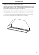
INTRODUCTION Thank you for purchasing a Fisher & Paykel product. Thousands of hours go into the design, engineering, testing and perfecting of each Fisher & Paykel appliance. The care and attention given to creating these beautiful products doesn’t stop once it has found its home with you.
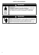
SAFETY AND WARNINGS ! 8.2 kg (HP60) WARNING! Weight Hazard The appliance is heavy. Please ensure adequate care is taken when installing the appliance to prevent personal injury. The appliance must be installed onto a solid wall, stud, beam or truss. Weight of the product is 8.2 kg (HP60) / 11.5 kg (HP90). 11.5 kg (HP90) ! WARNING! Electric Shock Hazard Always disconnect the appliance from the mains power supply before carrying out any maintenance or repairs.
SAFETY AND WARNINGS IMPORTANT SAFETY INSTRUCTIONS WARNING! When using this appliance always exercise basic safety precautions including the following: ●● ●● ●● ●● ●● ●● ●● ●● ●● ●● ●● ●● ●● ●● ●● ●● ●● Read the entire set of instructions before installing or using this appliance. Please make this information available to the person installing the appliance – doing so could reduce your installation costs.
SAFETY AND WARNINGS ●● ●● ●● ●● ●● ●● ●● ●● 6 You must read the details concerning the method and frequency of cleaning. There is a fire risk if cleaning is not carried out in accordance with the instructions. Never leave frying food unattended since grease can overheat and catch fire. The risk of fire is even greater in the case of used oil. Do not flambé under the rangehood. Never use the rangehood without the filters in place.
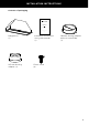
INSTALLATION INSTRUCTIONS Contents of packaging BUILT-IN INTEGRATED RANGEHOOD HP60IDCHX2, HP90IDCHX2, HP60IDCHX3 & HP90IDCHX3 models INSTALLATION GUIDE / USER GUIDE NZ AU ROW Rangehood (1) 125 mm ducting adapter (1) Installation instructions User guide manual (1) 150 mm ducting adapter with non return flap (1) 13 mm screw (2) 7
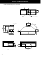
INSTALLATION INSTRUCTIONS Product and cabinetry cutout dimensions K J Ø L Power cord location H Ducting adapter I (A) A D G O F C E B M N N M HP60 8 HP90
INSTALLATION INSTRUCTIONS PRODUCT DIMENSIONS HP60 HP90 mm mm 350 (395) 315 (360) A Overall height of product (with ducting adapter) B Overall width of product 530 830 C Overall depth of product 280 280 D Thickness of flange 2 2 E Width of chassis 492 792 F Depth of chassis 255 255 G Height of side of chassis 120 120 H Width of top surface of chassis 220 220 I Length of angled surface of chassis 260 335 J Distance from centre of ducting outlet to back of chassis 14
INSTALLATION INSTRUCTIONS Height of rangehood P MINIMUM CLEARANCES P Height top of cooktop to base of product Electric cooktop Gas cooktop mm min. 600 – max. 750 min. 650 – max. 750 Rangehood installation height above the cooktop is the user’s preference. Lower installation heights will improve the efficiency of capturing cooking odours, grease, and smoke. This rangehood must be installed between the minimum and maximum dimensions indicated in the table above.
INSTALLATION INSTRUCTIONS Venting requirements IMPORTANT! To reduce risk of fire and to properly exhaust air, be sure to duct air outside — Do not vent exhaust air into spaces within walls or ceilings or into attics, crawl spaces, or garages. The range hood can be installed to operate with the exhaust air ducted externally from the kitchen or with the exhaust air recirculating within the kitchen. External venting ●● ●● For best results: Use the shortest and straightest duct route possible.
INSTALLATION INSTRUCTIONS IMPORTANT! Venting directly into the cabinet with no ducting and louvered vent is not permitted. 1 2 3 To recirculate your perimeter insert range hood: Determine the desired location of the 150mm louvered vent on your cabinetry. The louvered vent can be placed on the side or front of your cabinet provided there is sufficient clearance from the surrounding cabinetry to enable ventilated air to recirculate back into your kitchen.
INSTALLATION INSTRUCTIONS 1 3 2 4 360˚ 360˚ 360˚ 360˚ 360˚ 360˚ 5 6 13
INSTALLATION INSTRUCTIONS 5 Lift the rangehood and fit through the opening of the cupboard till the spring loaded brackets / clips hold the product in place. x4 6 Secure rangehood while tightening the 4 brackets / clips. x4 2.3 2.1 width 2.2 depth 7 Connect duct and plug rangehood in.
OPERATING INSTRUCTIONS Touch control panel CONTROL PANEL FEATURES Filter cleaning alert Activated regularly to alert of the need to clean filters. It can be deactivated with a single press. Timer Turn the timer on. The fan operates for 5 minutes at the current speed and each descending speed before turning off. Lights Turn the lights on or off. The lights turn on to the last level selected. Press and hold to adjust the level of light. Power on/off Turn the rangehood on or off.
CLEANING AND MAINTENANCE WARNING! ●● ●● Unplug or disconnect the appliance from the power supply before servicing or cleaning. When replacing the bulb, let the bulb cool, and assure that power to the rangehood has been turned off. Use new bulbs according to that indicated on the rangehood nameplate. IMPORTANT! ●● ●● Never use abrasive or oil based cleaners. Wear gloves to protect against sharp edges.
CLEANING AND MAINTENANCE Light bulb replacement ILCOS D code: DRR-3.5-220/240-GU10-50/50 1. To replace a light bulb, first disconnect the rangehood from its power supply. 2. Apply finger pressure to the face of the light bulb and twist one quarter turn anti-clockwise—the light bulb will now be free to drop out. 3. Remove the faulty bulb and fit replacement bulb into the lamp holder. 4. Refit the light bulb by applying finger pressure and twist one quarter turn clockwise.
PARTS AND ACCESSORIES ITEM LED bulb 792603 Aluminium filter 792429 Recirculation carbon filter x2 792481 Ducting 150 mm kit (eaves) Ducting 150 mm kit (wall) 18 REFERENCE NUMBER PD-RHK150E PD-RHK150W
CUSTOMER CARE Before you call for service or assistance... Check the things you can do yourself. Refer to your user guide and check that: 1 Your product is correctly installed. 2 You are familiar with its normal operation. If after checking these points you still need assistance or parts, please refer to your nearest Fisher & Paykel trained and supported service technician, Customer Care, or contact us through our local website listed on the back cover.
CUSTOMER CARE *If you call, write or contact our website please provide: your name and address, model number, serial number, date of purchase and a complete description of the problem. This information is needed in order to better respond to your request for assistance. Product details can be found on the inside of the chassis. The filter needs to be removed to be able to see them. Registration Register your product with us so we can provide you with the best service possible.
FISHERPAYKEL.COM © Fisher & Paykel Appliances 2019. All rights reserved. The product specifications in this document apply to the specific products and models described at the date of issue. Under our policy of continuous product improvement, these specifications may change at any time. You should therefore check with your Dealer to ensure this document correctly describes the product currently available. NZ AU ROW 104077E 06.