00809-0100-4737 English Rev.
Product Manual Models 244EH and 244ER PC-Programmable Temperature Transmitters NOTICE Read this manual before working with the product. For personal and system safety, and for optimum product performance, make sure you thoroughly understand the contents before installing, using, or maintaining this product. Within the United States, Rosemount Inc. has two toll-free assistance numbers: Customer Central Technical support, quoting, and order-related questions.
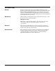
Table of Contents SECTION 1 Introduction Safety Messages . . . . . . . . . . . . . . . . . . . . . . . . . . . . . . . . . . . . . 1-1 Transmitter Overview . . . . . . . . . . . . . . . . . . . . . . . . . . . . . . . . . 1-1 Manual Overview . . . . . . . . . . . . . . . . . . . . . . . . . . . . . . . . . . . . 1-2 Considerations . . . . . . . . . . . . . . . . . . . . . . . . . . . . . . . . . . . . . . 1-3 General . . . . . . . . . . . . . . . . . . . . . . . . . . . . . . . . . . . . . . . . . .
Rosemount Models 244EH and 244ER PC-Programmable Temperature Transmitters APPENDIX A Reference Data Transmitter Specification . . . . . . . . . . . . . . . . . . . . . . . . . . . . . Functional. . . . . . . . . . . . . . . . . . . . . . . . . . . . . . . . . . . . . . . Performance . . . . . . . . . . . . . . . . . . . . . . . . . . . . . . . . . . . . . Physical . . . . . . . . . . . . . . . . . . . . . . . . . . . . . . . . . . . . . . . . Model 244EC Configuration Interface . . . . . . . . . . . . . .
Section 1 Introduction Safety Messages . . . . . . . . . . . . . . . . . . . . . . . . . . . . . . . . page 1-1 Transmitter Overview . . . . . . . . . . . . . . . . . . . . . . . . . . . . . page 1-1 Manual Overview . . . . . . . . . . . . . . . . . . . . . . . . . . . . . . . . page 1-2 Considerations . . . . . . . . . . . . . . . . . . . . . . . . . . . . . . . . . .
Rosemount Models 244EH and 244ER PC-Programmable Temperature Transmitters MANUAL OVERVIEW This manual is designed to assist in the installation, operation, and maintenance of Rosemount® Model 244EH and 244ER PC Programmable Temperature Transmitters and the Model 244EC Configuration Interface.
CONSIDERATIONS General Electrical temperature sensors such as RTDs and thermocouples produce low-level signals proportional to their sensed temperature. The Models 244EH and 244ER transmitters convert the low-level sensor signal to a standard 4–20 mA dc signal that is relatively insensitive to lead length and electrical noise. This current signal is then transmitted to the control room via two wires.
Section 2 Installation Safety Messages . . . . . . . . . . . . . . . . . . . . . . . . . . . . . . . . page 2-1 Tools needed for Installation . . . . . . . . . . . . . . . . . . . . . . . page 2-2 Mounting . . . . . . . . . . . . . . . . . . . . . . . . . . . . . . . . . . . . . . . page 2-3 Installation Procedures . . . . . . . . . . . . . . . . . . . . . . . . . . . page 2-5 Field Wiring . . . . . . . . . . . . . . . . . . . . . . . . . . . . . . . . . . . . . page 2-12 Failure Mode . . . . . . . . . . .
Rosemount Models 244EH and 244ER PC-Programmable Temperature Transmitters Figure 2-1.
MOUNTING The Model 244EH installs in a connection head or universal head mounted directly on a sensor assembly, apart from a sensor assembly using a universal head, or to a DIN rail using an optional mounting clip. The Model 244ER mounts directly to a wall or to a DIN rail. The Models 244EH and 244ER transmitters will operate within specifications for ambient temperatures between –40 and 185 °F (–40 and 85 °C).
Rosemount Models 244EH and 244ER PC-Programmable Temperature Transmitters Special Mounting Considerations Special mounting hardware is available for mounting a Model 244EH head mount transmitter to a DIN rail, or assembling a new Model 244EH to an existing threaded sensor connection head (former option code L1).
INSTALLATION PROCEDURES Transmitter Refer to the appropriate procedure and the accompanying illustrations when installing the transmitter. Head Mount Transmitter with DIN Plate Style Sensor The least complicated assembly uses: • an integral mount sensor with flying leads • an integral DIN style connection head • a standard extension • a threaded thermowell Refer to Volume 2 of the Rosemount Sensors Product Data Sheet (document number 00813-0101-2654) for complete sensor and mounting accessory information.
Rosemount Models 244EH and 244ER PC-Programmable Temperature Transmitters Head Mount Transmitter with Threaded Sensor The least complicated assembly uses: • a threaded sensor with flying leads • the universal connection head • a union and nipple extension assembly • a threaded thermowell Refer to Volume 1 of the Rosemount Sensors Product Data Sheet (document number 00813-0100-2654) for complete sensor and mounting accessory information. To complete the assembly, follow the steps as described below. 1.
Rail Mount Transmitter with Integral Mount Sensor The least complicated assembly uses: • an integral mount sensor with terminal block • an integral DIN style connection head • a standard extension • a threaded thermowell Refer to Volume 2 of the Rosemount Sensors Product Data Sheet (document number 00813-0101-2654) for complete sensor and mounting accessory information. To complete the assembly, follow the procedure described below. 1. Attach the transmitter to a suitable rail or panel. 2.
Rosemount Models 244EH and 244ER PC-Programmable Temperature Transmitters Rail Mount Transmitter with Threaded Sensor The least complicated assembly uses: • a threaded sensor with flying heads • a threaded sensor connection head • a union and nipple extension assembly • a threaded thermowell Refer to Volume 1 of the Rosemount Sensors Product Data Sheet (document number 00813-0100-2654) for complete sensor and mounting accessory information. To complete the assembly, follow the procedure described below. 1.
Multichannel Installations Several transmitters can be connected to a single master power supply as shown in Figure 2-9. In this case, the system may be grounded only at the negative power supply terminal. In multichannel installations where several transmitters depend on one power supply and the loss of all transmitters would cause operational problems, consider a back-up battery or power supply that cannot be interrupted.
Rosemount Models 244EH and 244ER PC-Programmable Temperature Transmitters Choose the procedure that matches the operating system you are using. Procedure for Windows 3.1 or Windows for Workgroups 3.11 1. If you do not have Win32s installed, install it now. Follow the instructions on the diskette label. 2. Insert the Models 244EH and 244ER Configuration Software diskette into your floppy disk drive. 3. In the File Manager, choose RUN from the FILE menu. 4. The RUN dialog box appears.
Screen Conventions The Models 244EH and 244ER Configuration Software follows the Microsoft Windows screen conventions with the following exception: Configuration parameters change color to indicate fields where information has changed. Before placing a new transmitter into service, or before returning a transmitter to service after changing configuration information, verify that the values in the fields that have been changed reflect the correct configuration parameters for your application.
Rosemount Models 244EH and 244ER PC-Programmable Temperature Transmitters 5. Turn on the Model 244EC using the power switch on the top side of the housing. NOTE Verify that the Model 244EC “Low Battery” LED is not on before initiating communication with the transmitter. If the low battery LED is on, you will not be able to configure the transmitter. 6. Using your PC, open the Configuration Software program. Access the online help if you have questions regarding the use of the program. Figure 2-10.
Use the following steps to wire the transmitter: 1. Connect the positive lead from the power supply to the transmitter terminal marked “+” and the negative lead to the transmitter terminal marked “–” (see Figure 2-11 and Figure 2-13). 2. Tighten the terminal compression screws to ensure adequate contact. No additional power wiring is required. 3. After making connections, recheck the polarity and correctness of connections, then turn the power on. Figure 2-11.
Rosemount Models 244EH and 244ER PC-Programmable Temperature Transmitters Sensor Lead Wire Resistance Effect RTD Input When using a 4-wire RTD, the effect of lead resistance is eliminated and has no impact on accuracy. However, a 3-wire sensor will not fully cancel lead resistance error because it cannot compensate for imbalances in resistance between the lead wires. Using the same type of wire on all three lead wires will make a 3-wire RTD installation as accurate as possible.
• Pt100 2-wire RTD: Lead Wire Resistance Basic Error = ---------------------------------------------------------( α Pt × R o ) ( α Cu ) × ( ∆T amb ) × ( Lead Wire Resistance ) Error due to amb. temp. variation = ---------------------------------------------------------------------------------------------------------------( α Pt ) × ( R o ) Lead wire resistance seen by the transmitter = 150 m × 2 wires × 0.025 Ω/m = 7.5 Ω 7.
Rosemount Models 244EH and 244ER PC-Programmable Temperature Transmitters Model 244EH Model 244ER Sensor Terminals 1 2 3 Sensor Terminal 4 Configuration Terminals Failure Mode Switch Failure Mode Switch Power/Configuration Terminals Power Terminal FAILURE MODE The Models 244EH and 244ER features software driven alarm diagnostics and an independent circuit. These features are designed to provide separate backup alarm output in case the microprocessor, electronics, hardware, or software fails.
Section 3 Operation Safety Messages . . . . . . . . . . . . . . . . . . . . . . . . . . . . . . . . page 3-1 Power Supply . . . . . . . . . . . . . . . . . . . . . . . . . . . . . . . . . . . page 3-1 Configuration . . . . . . . . . . . . . . . . . . . . . . . . . . . . . . . . . . . page 3-2 Intermittent Sensor Algorithm . . . . . . . . . . . . . . . . . . . . .
Rosemount Models 244EH and 244ER PC-Programmable Temperature Transmitters Grounding The transmitter will operate with the current signal loop either floating or grounded. However, the extra noise in floating systems affects many types of readout devices. If the signal appears noisy or erratic, grounding the current signal loop at a single point may solve the problem. The best place to ground the loop is at the negative terminal of the power supply.
Configuring a Single Transmitter NOTE See “Configuration Software” on page 2-9 for instructions on how to install the configuration software. To configure a single Model 244EH or 244ER transmitter, perform the following procedure: 1. Disconnect power to the transmitter if the transmitter is installed in a measurement loop. NOTE Configuring a transmitter while it is powered in a measurement loop could cause the Model 244EC to shunt the current. 2.
Rosemount Models 244EH and 244ER PC-Programmable Temperature Transmitters NOTE Each configuration parameter is explained in detail in the on-line help provided with the software. To access help, click the HELP button on the main configuration window (see Figure 3-1). 5. Click the SEND TO XMTR button to upload configuration information to the transmitter. The software will indicate whether the configuration is successful or unsuccessful. If the configuration succeeds, then go to step Step 6.
Viewing the Process Variable With version 2.0 and later of the Model 244EC Configuration Interface, users can view the measured temperature (PV) by selecting SERVICE from the menu bar of the main configuration window (see Figure 3-2). In order to view a valid PV, a temperature sensor must be connected to the Model 244E transmitter, and the transmitter must be configured properly for that sensor type. The PV will be automatically updated on the Model 244EC screen approximately two times per second.
Rosemount Models 244EH and 244ER PC-Programmable Temperature Transmitters Case Examples Case 1: Open Sensor If the algorithm detects an open sensor, the transmitter immediately goes into alarm (high or low, depending on the position of the failure mode switch).
Step Changes Greater than Threshold Value Input Total of All Step Changes Output without Algorithm Output with Algorithm (Default) 0 500 1000 1500 2000 2500 3000 3500 4000 Time (in 500 ms increments) D) If an open sensor is validated at the end of the first update cycle (Time = 500 ms), the output will go directly to alarm level. The original spike (at Time = 0 ms) will not be seen at the output.
Rosemount Models 244EH and 244ER PC-Programmable Temperature Transmitters Figure 4-1 illustrates an example of intermittent sensor detect with damping enabled. If the temperature undergoes a step change greater than the threshold value, or from 100 degrees to 110 degrees, and the damping is set to 5.0 seconds, the transmitter calculates a new reading every 500 ms using the damping equation, but holds the output at 100 degrees for between 1.75 and 2.0 seconds. Within 1.75 and 2.
Transmitter Behavior with Intermittent Sensor Detect ON When the Intermittent Sensor Detect feature is switched ON, the transmitter can eliminate the output pulse caused by intermittent open sensor conditions. Process temperature changes (∆T) within 2% of the output range will be tracked normally by the transmitter’s output. A ∆T greater than 2% of the output range will activate the intermittent sensor algorithm. True open sensor conditions will cause the transmitter to go into alarm.
Section 4 Maintenance and Troubleshooting Safety Information . . . . . . . . . . . . . . . . . . . . . . . . . . . . . . . page 4-1 Troubleshooting . . . . . . . . . . . . . . . . . . . . . . . . . . . . . . . . . page 4-1 SAFETY INFORMATION Procedures and instructions in this manual may require special precautions to ensure the safety of the personnel performing the operations. Information that raises potential safety issues is indicated by a warning symbol ( ).
Rosemount Models 244EH and 244ER PC-Programmable Temperature Transmitters The “Information Transmitter UNSUCCESSFUL” message appears because the transmitter did not accept the change made in the Intermittent Sensor Detect field. However, any other configuration changes sent at the same time as the Intermittent Sensor Direct change will be sent successfully. These other configuration changes can be verified by clicking on the READ XMTR button. TABLE 4-1.
Appendix A Reference Data Transmitter Specification . . . . . . . . . . . . . . . . . . . . . . . . . . page A-1 Ordering Information . . . . . . . . . . . . . . . . . . . . . . . . . . . . . page A-6 Dimensional Drawings . . . . . . . . . . . . . . . . . . . . . . . . . . . . page A-9 TRANSMITTER SPECIFICATION Inputs User selectable using the Model 244EC Configuration Interface and the Models 244EH and 244ER configuration software; sensor terminals rated to 42.4 V dc. See Table A-2 on page A-3.
Rosemount Models 244EH and 244ER PC-Programmable Temperature Transmitters Failure Mode The values that the transmitter drives its output to in failure mode depend on whether it is factory configured to standard or NAMUR-compliant operation. The values for standard and NAMUR-compliant are as follows: TABLE A-1. Operation Parameters Standard Linear Output: Fail High: Fail Low: NAMUR-Compliant 3.9 ≤ I ≤ 20.5 mA 21 ≤ I ≤ 23 mA (default) I ≤ 3.75 mA 3.8 ≤ I ≤ 20.5 mA 21 ≤ I ≤ 23 mA (default) I ≤ 3.
Accuracy TABLE A-2. Model 244E Input Options and Accuracy. Sensor Options Sensor Reference Input Ranges 2-, 3-, 4-wire RTDs Pt 100 IEC 751, 1995 (α = 0.00385) Pt 100 JIS 1604, 1981 (α = 0.003916) Pt 200 IEC 751, 1995 (α = 0.00385) PT 500 IEC 751, 1995 (α = 0.00385) Pt 1000 IEC 751, 1995 (α = 0.00385) Ni 120 Edison Curve No. 7 Cu 10 Edison Copper Winding No.
Rosemount Models 244EH and 244ER PC-Programmable Temperature Transmitters Ambient Temperature Effect Transmitters can be installed in locations where the ambient temperature is between –40 and 85 °C (–40 and 185 °F). At the factory, each transmitter is individually characterized over this ambient temperate range. This special manufacturing technique is accomplished through hot and cold temperature profiling with individual adjustment factors programmed into each transmitter.
Physical Electrical Connections Power and Sensor Terminals Model 244EH Compression screws permanently Clips permanently fixed to fixed to terminal block terminal block Model 244ER: Compression screw permanently Clips permanently fixed to fixed to front panel front panel WAGO® spring clamp terminals are optional (option code G5) Materials of Construction Construction Material for the Electronics Housing and Terminal Block Model 644H Model 644R: Noryl® glass reinforced Lexan® polycarbonate Mounting The M
Rosemount Models 244EH and 244ER PC-Programmable Temperature Transmitters ORDERING INFORMATION TABLE A-4.
TABLE A-5. Model 244EC Configuration Interface Ordering Information • = Available — = Not available Model Product Description 244EC Model 244EC Configuration Interface Hardware and Software Typical Model Number: 244EH • 244EC TABLE A-6. Transmitter Accessories Part Description Aluminum Allow Universal Head, Standard Cover—M20 Entries Aluminum Allow Universal Head, Standard Cover—1/2-14 NPT Entries Ground Screw Assembly Kit Models 244EH and 244ER Configuration Software (Four 3.
Rosemount Models 244EH and 244ER PC-Programmable Temperature Transmitters Ordering Flameproof and Explosion-proof Approvals for Temperature Assemblies Both flameproof and explosion-proof protection depend on the enclosure type. Compliance with flameproof and explosion-proof approvals requires an appropriately approved assembly, including the sensor. The Model 244EH requires an appropriate enclosure for approved use in locations requiring flameproof or explosion-proof installations.
DIMENSIONAL DRAWINGS Transmitter Model 244ER Model 244EH Shown with Standard Compression Screw Terminals 60 (2.4) 33 (1.3) Sensor Terminals WAGO® Spring Clamp Sensor Terminals Communication Terminals Power Terminals Failure Mode Switch Power Terminals 33 (1.30) 644-1360B02A 24 (1.0) 104 (4.1) 36 (1.4) 60 (2.4) 33 (1.3) Standard Sensor Terminals 24 (1.0) Communication Terminals Failure Mode Switch Power Terminals 34 (1.33) 644-1360A02A 82 (3.2) 644-1105E01A.
Appendix B Approvals Safety Messages . . . . . . . . . . . . . . . . . . . . . . . . . . . . . . . . page B-1 Hazardous Locations Installations . . . . . . . . . . . . . . . . . . page B-1 Locations Certifications . . . . . . . . . . . . . . . . . . . . . . . . . . page B-2 Installation Drawings . . . . . . . . . . . . . . . . . . . . . . . . . . . . .
Rosemount Models 244EH and 244ER PC-Programmable Temperature Transmitters LOCATIONS CERTIFICATIONS Factory Mutual (FM) Approvals E5 Explosion-Proof for Class I, Division 1, Groups B, C, and D. Dust-Ignition Proof for Class II, Division 1, Groups E, F, and G. Dust-Ignition Proof for Class III, Division 1 hazardous locations when installed in accordance with Rosemount Drawing 00644-1049. Non-Incendive for Class I, Division 2, Groups A, B, C, and D. Ambient temperature limits: –50 to 85 °C.
KEMA Approvals ED ATEX II 2 G Flameproof (Zone 1) (Model 244EH only) EEx d IIC T6 (Tamb = –40 to 65 °C). NOTE: Flameproof certification is only available as a complete assembly with Rosemount universal head – option codes J5 or J6.
Rosemount Models 244EH and 244ER PC-Programmable Temperature Transmitters N7 Type N Approval, Ex n IIC T5 (Tamb = 70 °C) Special Conditions for Safe Use (X): The assembly must be installed such that its external terminals and communication pins are protected to at least the requirements of IP54. E7 Flameproof Approval (Model 244EH only) Ex d IIC T6 NOTE: Flameproof certification is only available as a complete assembly with Rosemount universal head – option codes J5 or J6.
Figure B-1. Canadian Standards Association (CSA) Intrinsic Safety Installation Drawing 00644-1064, Rev.
Rosemount Models 244EH and 244ER PC-Programmable Temperature Transmitters 644-1059A01A Figure B-2. Canadian Standards Association (CSA) Explosion-Proof Installation Drawing 00644-1059, Rev.
644-0009A01A Figure B-3. Factory Mutual (FM) Intrinsic Safety Installation Drawing 00644-0009, Rev.
Rosemount Models 244EH and 244ER PC-Programmable Temperature Transmitters 644-1049A01A Figure B-4. Factory Mutual (FM) Explosion-Proof Installation Drawing 00644-1049, Rev.
Appendix C Models 644 and 244E Temperature Transmitters Manual Supplement Old Transmitter . . . . . . . . . . . . . . . . . . . . . . . . . . . . . . . . . . page C-2 New Transmitter . . . . . . . . . . . . . . . . . . . . . . . . . . . . . . . . . page C-3 Specifications . . . . . . . . . . . . . . . . . . . . . . . . . . . . . . . . . . . page C-4 This manual supplement is intended to indicate the primary differences between the old and new Models 644 and 244E.
Rosemount Models 244EH and 244ER PC-Programmable Temperature Transmitters OLD TRANSMITTER OLD TRANSMITTER Transmitter Design Models 644H and 244EH Models 644R and 244ER Two Mounting Holes Sensor Wiring Diagrams 1 2 34 2-wire RTD and V 1 2 3 4 1 2 3 4 1 2 3 4 3-wire * RTD with** 4-wire RTD Comp. RTD and V Loop and V 644-0000B01B Models 644 and 244E 12 3 4 T/C and mV * Rosemount Inc. provides 4-wire sensors for all single element RTDs.
NEW TRANSMITTER NEW TRANSMITTER Transmitter Design Models 644H and 244EH Models 644R and 244ER 644, 244-1360A02B Captive Mounting Screws and Springs Hole in Middle of Transmitter Meter Connector (Model 644H only) Sensor Wiring Diagrams 1 2 34 2-wire RTD and V 1 2 34 1 2 3 4 644-0000B01C Models 644 and 244E 1 23 4 1 234 3-wire * RTD with** 4-wire RTD Comp. RTD and V Loop and V T/C and mV * Rosemount Inc. provides 4-wire sensors for all single element RTDs.
Rosemount Models 244EH and 244ER PC-Programmable Temperature Transmitters SPECIFICATIONS Old New BASEFFA(1) Intrinsically Safe Installation Entity Parameters: Power Loop Group II C Zones 0 and 1 Sensor Umax:in Imax:in Wmax:in Ceq Li Uo Io Po Cable Load Co (µF) Lo (mH) 30 V dc 200 mA 1.0 W 30 V dc 200 mA 1.0 W 0.67 W • T5 (– 40 ≤ Ta ≤ 40 °C) • • T5 (– 60 ≤ Ta ≤ 40 °C) • T6 (– 60 ≤ Ta ≤ 40 °C) • T4 (– 40 ≤ Ta ≤ 80 °C) • • T4 (– 60 ≤ Ta ≤ 80 °C) • T5 (– 60 ≤ Ta ≤ 50 °C) 13.4 nF 0 µH 24.
Index A H Alarm see Failure mode Ambient Temperature . . . . . . . . A-4 Approvals . . . . . . . . . . . . . . . . . B-1 Humidity 244EC, limits for . . . . . . . . A-5 Transmitters . . . . . . . . . . . A-2 I C Changing Switch Positions . . . 2-16 Configuration . . . . . . . . . . . . . . 3-2 244EC Interface Ambient temperature . . A-5 Humidity limits . . . . . . A-5 Custom . . . . . . . . . . . . . . . A-8 Process variable . . . . . . . . . 3-5 Single Transmitter . . . . . . . 3-3 Standard . . . . . .
Rosemount Model 3244MV MultiVariable Temperature Transmitter with Profibus-PA Wiring diagrams . . . . . . . . . . . . . 2-13 Sensors diagram . . . . . . . 2-15 terminal . . . . . . . . . . . . . .
Rosemount Inc. 8200 Market Boulevard Chanhassen, MN 55317 USA Tel 1-800-999-9307 Fax (952) 949-7001 PR INT IN U. S. A. ED © Rosemount Inc., 2000 Fisher-Rosemount Limited Heath Place Bognor Regis West Sussex PO22 9SH England Tel 44 (1243) 863 121 Fax 44 (1243) 867 5541 ¢00809-0100-4737f¤ 00809-0100-4737 Rev EA 10/00 Fisher-Rosemount Singapore Pte Ltd. 1 Pandan Crescent Singapore 128461 Tel (65) 777-8211 Fax 65 777-0947 AP.RMT-Specialist@frco.com Product documentation available at... www.rosemount.