
Weather Radio User Manual


2-11
Screen Conventions
The Models 244EH and 244ER Configuration Software follows the
Microsoft Windows screen conventions with the following exception:
Configuration parameters change color to indicate fields where
information has changed. Before placing a new transmitter into service,
or before returning a transmitter to service after changing
configuration information, verify that the values in the fields that have
been changed reflect the correct configuration parameters for your
application. For example, if you change the Sensor Type field to PT100–
Alpha 392, the Number of Wires, Units, 4 mA Point, and 20 mA Point
fields all change to reflect the default PT100–Alpha 392 sensor values.
Verify all information before placing the transmitter into service.
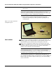
Model 244EC Configuration
Interface
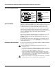
The Model 244EC Configuration Interface is a portable, self-contained
link between your PC and a Model 244. The Model 244EC connects to a
PC serial port with a standard 9-pin interconnecting plug and connects
to a transmitter with two MINIGRABBER
™
clips.
The Model 244EC will also operate using a wall power adapter or a
single replaceable 9-volt battery.
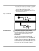
Setting Up the Model 244EC Configuration Interface
All necessary power is provided through the configuration leads from
the Model 244EC to the transmitter. The sensor does not need to be
disconnected in order to configure the transmitter.
To set up the Model 244EC Configuration Interface and prepare it for
use, refer to Figure 2-10 on page 2-12 and follow the procedure
described below.
1. Install the 9-volt battery in the Model 244EC. Be sure the power
switch remains in the “OFF” position.
2. Attach the ribbon cable from the Model 244EC to the serial port of
your PC using the 9-pin interconnecting plug. If your PC has a
25-pin serial port, you will need a 25-pin to 9-pin adapter to
accommodate the connection.
NOTE
It is not necessary to power down your PC before you attach the
Model 244EC. However, if you are using a desktop model, you may wish
to power down to reduce the risk of electric shock or computer damage.
3. Attach the configuration leads to the Model 244EC using the
banana jacks provided. Be sure to observe proper polarity—attach
the red lead to the positive (+) jack on the Model 244EC and the
black lead to the negative (–) jack.
4. Attach the configuration leads to the configuration terminals
(labeled “PROG”) on the transmitter using the MINIGRABBER
clips provided. Be sure to observe proper polarity—attach the red
lead to the positive (+) terminal on the transmitter and the black
lead to the negative (–) terminal.