
Weather Radio User Manual


Rosemount Models 244EH and 244ER PC-Programmable Temperature Transmitters
2-12
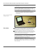
5. Turn on the Model 244EC using the power switch on the top side of
the housing.
NOTE
Verify that the Model 244EC “Low Battery” LED is not on before
initiating communication with the transmitter. If the low battery LED
is on, you will not be able to configure the transmitter.
6. Using your PC, open the Configuration Software program.
Access the online help if you have questions regarding the use
of the program.
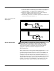
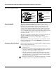
Figure 2-10. Complete Transmitter
Configuration System
FIELD WIRING All power to the transmitter is supplied over the signal wiring. Use
ordinary copper wire of sufficient size to ensure that the voltage across
the transmitter power terminals does not drop below 12.0 V dc.
If the sensor is installed in a high-voltage environment and a fault
condition or installation error occurs, the sensor leads and transmitter
terminals could carry lethal voltages. Use extreme caution when
making contact with the leads and terminals.
NOTE
Do not apply high voltage (e.g., ac line voltage) to the transmitter
terminals. Abnormally high voltage can damage the unit. (Sensor and
transmitter power terminals are rated to 42.4 V dc.)
For multichannel installations, see “Multichannel Installations” on
page 2-9. The transmitters will accept inputs from a variety of RTD and
thermocouple types. Refer to Figure 2-12 on page 2-15 when making
sensor connections.
Model 244EC
Configuration
Interface
Model 244EH or 244ER
Transmitter
Windows-based PC Running
the Configuration Software
244-011AB