Multimedia Projector MODEL PLC-XU07N Owner's Manual
INFORMATION TO THE USER NOTE : This equipment has been tested and found to comply with the limits for a Class A digital device, pursuant to Part 15 of FCC Rules. These limits are designed to provide reasonable protection against harmful interference when the equipment is operated in a commercial environment. This equipment generates, uses, and can radiate radio frequency energy and, if not installed and used in accordance with the instruction manual, may cause harmful interference to radio communications.
IMPORTANT SAFETY INSTRUCTIONS All the safety and operating instructions should be read before the product is operated. Read all of the instructions given here and retain them for later use. Unplug this projector from AC power supply before cleaning. Do not use liquid or aerosol cleaners. Use a damp cloth for cleaning. Do not use attachments not recommended by the manufacturer as they may cause hazards. Do not place this projector on an unstable cart, stand, or table.
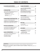
TABLE OF CONTENTS FEATURES AND DESIGN 5 PREPARATION 6 NAME OF EACH PART OF THE PROJECTOR SETTING-UP THE PROJECTOR 6 7 POSITIONING THE PROJECTOR ADJUSTABLE FEET CONNECTING THE AC POWER CORD VENTILATION MOVING THE PROJECTOR 8 8 8 8 9 CONNECTING THE PROJECTOR 10 TERMINALS OF THE PROJECTOR CONNECTING TO THE VIDEO EQUIPMENT CONNECTING TO THE IBM-COMPATIBLE COMPUTER CONNECTING TO THE MACINTOSH COMPUTER 10 11 12 14 BEFORE OPERATION 16 OPERATION OF THE REMOTE CONTROL TOP CONTROLS AND INDICATORS OPERAT
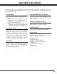
FEATURES AND DESIGN This Multimedia Projector is designed with most advance technology for portability, durability, and ease for use. The projector utilizes built-in multimedia features, a palette of 16.77 million colors, and matrix liquid crystal display (LCD) technology. ◆ Compatibility This projector is compatible with many different types of personal computers and video devices, including; ● IBM-compatible computers, including laptops, up to 1280 x 1024 resolution.
PREPARATION NAME OF EACH PART OF THE PROJECTOR FRONT OF THE CABINET PROJECTION LENS INFRARED REMOTE RECEIVER SPEAKER (Monaural) LENS COVER BACK OF THE CABINET EXHAUST VENT HOT AIR EXHAUSTED ! Air blown from the exhaust vent is hot. When using or installing the projector, following attention should be taken. ● Do not put a flammable object near this part. Keep heat-sensitive objects away from the exhaust vent. ● Do not touch this part especially screws and metallic parts.
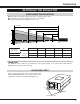
PREPARATION SETTING-UP THE PROJECTOR POSITIONING THE PROJECTOR ● This projector is basically designed to project on a flat projection surface. ● The projector can be focused from 4.6'(1.4m) ~ 35.4'(10.8m). ● Refer to the figure below to adjust the screen size. 35.4' (10.8m) 24.0' (7.3m) 300" 18.0' (5.5m) 200" H1 11.8' (3.6m) 230" 150" 4.6' (1.
PREPARATION VENTILATION This projector is equipped cooling fans for protection from overheating. Pay attention to the following to ensure the ventilation and avoid a possible risk of fire and malfunction. ● Do not cover the vent slot. ● Keep the rear grill at least one meter away from any object. ● Make sure that there is no object under the projector. An obstacle under the projector may prevent the projector from taking the cooling air through the bottom vent slot.
PREPARATION MOVING THE PROJECTOR Use the Carry Handle when moving the Projector. ● Replace the lens cover and rotate the feet fully clockwise (to shorten the feet) when moving the projector to prevent damage to the cabinet. NOTE The carrying bag (supplied) is intended for protection from dust and scratches on the surface of the cabinet, and it is not designed to protect the LCD projector from external shock.
CONNECTING THE PROJECTOR TERMINALS OF THE PROJECTOR COMPUTER INPUT TERMINAL MONITOR OUTPUT TERMINAL Connect the computer output to this terminal. (Refer to P12 ~15.) Connect to the monitor to this terminal. (Refer to P12 ~15.) SERIAL PORT CONNECTOR CONTROL PORT CONNECTOR When controlling the computer with the Remote Control of this projector, connect the mouse port to this connector. (Refer to P12 ~15.
CONNECTING THE PROJECTOR CONNECTING TO THE VIDEO EQUIPMENT Satellite TV Turner Video Cassette Recorder Video Disc Player Video / Audio Output S-VIDEO Output Used cables for connection • VIDEO CABLE ✽ • S-VIDEO CABLE ✽ • AUDIO CABLE (stereo) ✽ ✽ These cables are not supplied with this projector. Video Audio Cable ✽ Use the either of VIDEO jack or S-VIDEO jack. When the both jacks are connected, the S-VIDEO jack has priority over the VIDEO jack.
CONNECTING THE PROJECTOR CONNECTING TO THE IBM-COMPATIBLE COMPUTER To connect with the IBM-compatible computer, refer to the figure below. Used cables for connection • VGA CABLE • CONTROL CABLE FOR PS/2 PORT • CONTROL CABLE FOR SERIAL PORT ✽ • MONITOR CABLE ✽ • PC AUDIO CABLE (stereo) ✽ ✽ These cables are not supplied with this projector. NOTE : When connecting the cable, the power cords of both the projector and the external equipment should be disconnected from AC outlet.
CONNECTING THE PROJECTOR MONITOR OUT COMPUTER IN CONTROL PORT AUDIO IN R-AUDIO-L VIDEO SERIAL AUDIO OUT ▼ S-VIDEO (MONO) CONTROL PORT AUDIO IN AUDIO OUT MONITOR OUT A SERIAL B COMPUTER IN To disconnect MOUSE CABLE, 1. Hold the portion (B) of the connector with one hand. 2. Pull the portion (A) to the arrow direction and remove connector. Use either of these Mouse Cables corresponding with your terminal of your computer.
CONNECTING THE PROJECTOR CONNECTION TO THE MACINTOSH COMPUTER To connect with the Macintosh computer, refer to the figure below. Used cables for connection • VGA CABLE • CONTROL CABLE FOR ADB PORT ✽ • MAC ADAPTER ✽ • MONITOR CABLE ✽ • PC AUDIO CABLE (stereo) ✽ ✽ These cables are not supplied with this projector. NOTE : When connecting the cable, the power cords of both the projector and the external equipment should be disconnected from AC outlet.
CONNECTING THE PROJECTOR ◆ MAC/VGA ADAPTER (not supplied) Set the switches as shown in the table below dependON ing on the RESOLUTION MODE that you want to use before your turn on the OFF projector and computer.
BEFORE OPERATION OPERATION OF THE REMOTE CONTROL This remote control unit is not only able to operate the projector but also usable as a wireless mouse for a PC. POINT button and two CLICK buttons are used for wireless mouse operation. (Refer to page 33.) Wireless mouse is usable when PC mouse pointer is displayed on the screen, the wireless mouse cannot be used when the On-Screen Menu is displayed. ZOOM BUTTONS POWER ON-OFF BUTTON Used to adjust zoom. (P22) Used to turn the projector on or off.
BEFORE OPERATION Remote Control Batteries Installation 1 Remove the battery compartment lid. 2 Slide the batteries into the compartment. 3 Replace the compartment lid. Press the lid downward and slide it. Slide the lid upward. For correct polarity (+ and –), be sure the battery terminals are in contact with the pins in the compartment. To insure safe operation, please observe the following precautions : ● Use (2) AA type alkaline batteries. ● Replace two batteries at the same time.
BEFORE OPERATION TOP CONTROLS AND INDICATORS TEMPERATURE WARNING INDICATOR LAMP REPLACE INDICATOR This indicator turns to yellow when the life of the projection lamp draws to an end. (Refer to P35.) This indicator flashes red when internal projector temperature is too high. (Refer to P34.) LAMP REPLACE READY INDICATOR This indicator is lit in green when the projector is ready to be turned on. WARNING TEMP. READY LAMP INDICATOR This indicator is lit in dim when the projector is turned on.
BEFORE OPERATION OPERATING ON-SCREEN MENU HOW TO OPERATE ON-SCREEN MENU You can control and adjust this projector through ON-SCREEN MENU. Refer to the following pages to operate the each adjustment on the ON-SCREEN MENU. WIRELESS REMOTE CONTROL POINT BUTTON Used to move the Pointer to UP/ DOWN/ RIGHT/ LEFT. 1 MOVING THE POINTER Move the pointer (see the NOTE below) by pressing POINT button(s) on the Top Control or on the Remote Control Unit. 2 SELECT THE ITEM SELECT BUTTON Used to select the item.
BEFORE OPERATION MENU BAR MENU BAR IN COMPUTER MODE MODE MENU Used to select the Computer input mode. (Refer to P24) AUTO IMAGE MENU PC ADJUST MENU SETTING MENU Used to adjust Fine sync., Total dots, and Picture Position automatically. (Refer to P28) Used to adjust the parameters to match with the input signal format. (Refer to P25) Used to set the Display Menu and to reset Lamp Replacement Monitor Timer. (Refer to P32) LANGUAGE MENU Used to select the language used in the Menu.
BASIC OPERATIONS TURNING ON / OFF THE PROJECTOR Turning on the Projector 1 Complete the peripheral connections (with Computer, VCR, and etc.) before turning on the projector. (Refer to "CONNECTING TO THE PROJECTOR" on Pages 10~15 for connecting those equipment. 2 Connect the projector's AC power cord into a wall outlet. The LAMP POWER indicator lights RED, and the READY indicator lights GREEN. 3 Press the power ON-OFF button on the Remote Control Unit or on the Top Control to ON.
BASIC OPERATION ADJUSTING THE PICTURE ZOOM Adjustment 1 Press ZOOM / button on the Remote Control Unit or ZOOM ▲/▼ button on the Top Control to turn into the ZOOM mode. 2 Press ZOOM or ▲ button to have the image larger, and press ZOOM or ▼ button to have the smaller. Zoom The message disappears after 4 seconds. FOCUS Adjustment 1 Press FOCUS / button on the Remote Control Unit or FOCUS ▲/▼ on the Top Control to turn into the FOCUS mode.
BASIC OPERATION SOUND ADJUSTMENT Direct Operation It indicates the roughly level of the volume. Sound Volume Adjustment Press the VOLUME (+/–) buttons (located on the Top Control or on the Remote Control Unit) to adjust the volume. The Volume dialog box appears on the screen for a few seconds. (+) button to increase the volume, and (–) button decreasing. Sound Mute Setting Press the MUTE button on the Remote Control Unit to cut off the sound.
COMPUTER MODE SELECTING COMPUTER MODE Direct Operation Press the MODE button on the Top Control or the Remote Control Unit. The input source is selected among COMPUTER or VIDEO. The “Computer” or “Video” display will appear on the screen for a few seconds. Computer Video Menu Operation Press the MENU button and the ON-SCREEN MENU will appear. Press the POINT LEFT/RIGHT buttons to select Computer and press the SELECT button.
COMPUTER MODE PC ADJUSTMENT This Projector can automatically detect display signals from most personal computers currently distributed. However, some computers employ special signal formats which are different from the standard ones and may not be detected by this projector. If this happens, the projector cannot reproduce a proper image and the image is recognized as a flickering picture, a non-synchronized picture, a non-centered picture or a skewed picture.
COMPUTER MODE COMPATIBLE COMPUTER SPECIFICATIONS Basically this projector can accept the signal from all computers with the V, H-Frequency below mentioned and less than 165 MHz of Dot Clock. V-Freq. (Hz) 59.88 ON-SCREEN DISPLAY RESOLUTION 640 x 480 H-Freq. (kHz) 31.47 XGA 5 VGA 2 720 x 400 31.47 70.09 VGA 3 640 x 400 31.47 VGA 4 640 x 480 37.86 ON-SCREEN DISPLAY RESOLUTION VGA 1 1024 x 768 H-Freq. (kHz) 60.31 V-Freq. (Hz) 74.92 XGA 6 1024 x 768 48.50 60.02 70.
COMPUTER MODE PICTURE IMAGE ADJUSTMENT Adjust Picture Image Manually 1 Press the MENU button and the ON-SCREEN MENU will appear. Press the POINT LEFT/RIGHT buttons to select IMAGE and press the SELECT button. Another dialog box PICTURE IMAGE ADJUSTMENT Menu will appear. 2 Press the POINT DOWN button and a red-arrow icon will appear. Move the arrow to ▲ or ▼ of the item that you want to change by pressing the POINT UP/DOWN buttons.
COMPUTER MODE Auto Image Function The Auto Image function is provided to automatically adjust Fine sync., Total dots, and Picture Position for most computers. 1 Press the MENU button and the ON-SCREEN MENU will appear. Press the POINT LEFT/RIGHT buttons to select AUTO IMAGE and press the SELECT button. Another dialog box AUTO IMAGE Menu will appear. 2 Move the arrow to an item that you want to adjust by pressing the POINT UP/DOWN button. Change the setting On or Off by pressing the SELECT button.
COMPUTER MODE PICTURE POSITION ADJUSTMENT The position of the image can be adjusted vertically and horizontally through PICTURE POSITION ADJUSTMENT. 1 Press the MENU button and the ON-SCREEN MENU will appear. Press the POINT LEFT/RIGHT buttons to select POSITION and press the SELECT button. Another dialog box PICTURE POSITION Menu will appear. 2 Select the arrow to the direction (described as , , or ) that you want to adjust by pressing the POINT UP/DOWN buttons, and then press the SELECT button.
VIDEO MODE SELECTING VIDEO MODE Direct Operation Video Press the MODE button on the Top Control or the Remote Control Unit. The input source is selected among VIDEO or COMPUTER. The “Video” or “Computer” display will appear on the screen for a few seconds. Computer Menu Operation Press the MENU button and the ON-SCREEN MENU will appear. Press the POINT LEFT/RIGHT buttons to select Video and press the SELECT button. SELECTING COLOR SYSTEM 1 Press the MENU button and the ON-SCREEN MENU will appear.
VIDEO MODE PICTURE IMAGE ADJUSTMENT Adjusting the Picture Image 1 Press the MENU button and the ON-SCREEN MENU will appear. Press the POINT LEFT/RIGHT buttons to select IMAGE and press the SELECT button. Another dialog box PICTURE IMAGE ADJUSTMENT Menu will appear. 2 Press the POINT DOWN button and a red-arrow icon will appear. Move the arrow to ▲ or ▼ of the item that you want to change by pressing the POINT UP/DOWN buttons. To increase the value, point the arrow to ▲ and then press the SELECT button.
SETTING SETTING MENU 1 Press the MENU button and the ON-SCREEN MENU will appear. Press the POINT LEFT/RIGHT buttons to select SETTING and press the SELECT button. Another dialog box SETTING Menu will appear. 2 Press the POINT DOWN button and a red-arrow icon will appear. Move the arrow to the item that you want to set, and then press the SELECT button to set it "On" or "Off".
APPENDIX OPERATING WIRELESS MOUSE The Wireless Remote Control Unit is not only able to operate the projector but also usable as a wireless mouse for a PC. POINT buttons and two CLICK buttons are used for wireless mouse operation. Wireless mouse is usable when PC mouse pointer is displayed on the screen. When the menu or indicator of the projector is displayed on the screen instead of the PC mouse pointer, the wireless mouse cannot be used.
APPENDIX MAINTENANCE TEMPERATURE WARNING INDICATOR The TEMPERATURE WARNING Indicator flashes red when the internal temperature of the projector exceeds the normal temperature. The Indicator stops to flash when the temperature of the projector become normal. When the TEMPERATURE WARNING Indicator continues to flash, make sure the matters below. 1 The Ventilation slots of the projector are blocked. In such an event, reposition the appliance so that the ventilation slots are not obstructed.
APPENDIX LAMP REPLACEMENT Indicator When the Lamp of this projector draws to an end, the LAMP REPLACEMENT indicator lights yellow. When the image become dark or the color of the image become unnatural, replacement of the Lamp is required. LAMP REPLACEMENT CAUTION ● For continued safety, replace with a lamp assembly of the same type. ● Allow the projector to cool for at least 45 minutes before you open the lamp cover. The inside of the projector can become very hot.
APPENDIX TROUBLESHOOTING Before calling your dealer or service station for assistance, check the matters below once again. 1. Make sure you have connected the projector to your equipment a s described in section "CONNECTING THE PROJECTOR" on pages 10 ~ 15. 2. Check cable connection. Verify that all computer, video and power cord are properly connected. 3. Verify that all power is switched on. 4. If the projector still does not produce the image, re-start the computer. 5.
APPENDIX WARNING : High voltages are used to operate this projector. Do not attempt to open the cabinet. Sanyo Service is easily obtained.
TECHNICAL SPECIFICATIONS Projector Type Dimensions (W x H x D) Net Weight LCD Panel System Panel Resolution Number of Pixels Color System Scanning Frequency Projection Image size (Diagonal) Horizontal Resolution Projection Lens Throw Distance Projection Lamp AV Input Jacks Computer Input Jacks Control Port Jack Serial Port Monitor Output Jack Computer Audio Input Jack Audio Output Jack Internal Audio Amp Built-in Speaker Feet Adjustment Voltage Power Consumption Operating Temperature Storage Temperature Rem
OPTIONAL PARTS The parts listed below are optionally supplied. When ordering those parts, give the name and the Type No. of it to the sales dealer. ● Control Cable for Serial Port Type No. : POA-MC12SRL ● Control Cable for ADB Port Type No. : POA-MC12MAC ● MAC Adapter Type No.
SANYO INDUSTRIAL VIDEO LCD PROJECTOR LIMITED WARRANTY OBLIGATIONS In order to obtain warranty service, the product must be delivered to and picked up from and Authorized Sanyo Factory Service Center at the user's expense, unless specifically stated otherwise in this warranty. the names and addresses of authorized Sanyo Service Centers may be obtained by calling the toll-free number listed below.