Multimedia Projector MODEL PLC-XU87 PLC-XU84 Network Supported ❏Wireless LAN IEEE802.11b/g ❏Wired LAN 100-Base-TX/10-Base-T Memory Viewer ❏USB Memory Viewer (optionally available) Compatible with a dedicated USB memory ✽Refer to the owner’s manuals below for details about network and memory viewer function. ■Network Set-up and Operation ■Owner's Manual USB Memory This manual is provided with optionally supplied USB memory.
Features and Design This Multimedia Projector is designed with the most advanced technology for portability, durability, and ease of use. This projector utilizes built-in multimedia features, a palette of 16.77 million colors, and matrix liquid crystal display (LCD) technology. ◆ Compact Design ◆ This projector is designed compact in size and weight. It is easy to carry and installed anywhere you wish to use.
Table of Contents Features and Design . . . . . . . . . . . . . . . . . . .2 Table of Contents . . . . . . . . . . . . . . . . . . . . . .3 To the Owner . . . . . . . . . . . . . . . . . . . . . . . . .4 Safety Instructions . . . . . . . . . . . . . . . . . . . .5 Air Circulation Moving the Projector Installing the Projector in Proper Directions 6 6 7 Compliance . . . . . . . . . . . . . . . . . . . . . . . . . .8 Part Names and Functions . . . . . . . . . . . . . .
To the Owner Before installing and operating this projector, read this manual thoroughly. This projector provides many convenient features and functions. Operating the projector properly enables you to manage those features and maintains it in good condition for many years to come. Improper operation may result in not only shortening the product-life, but also malfunctions, fire hazard, or other accidents.
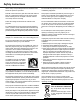
Safety Instructions All the safety and operating instructions should be read before the product is operated. Do not install the projector near the ventilation duct of airconditioning equipment. Read all of the instructions given here and retain them for later use. Unplug this projector from AC power supply before cleaning. Do not use liquid or aerosol cleaners. Use a damp cloth for cleaning. This projector should be operated only from the type of power source indicated on the marking label.
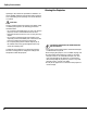
Safety Instructions Moving the Projector Openings in the cabinet are provided for ventilation. To ensure reliable operation of the product and to protect it from overheating, these openings must not be blocked or covered. CAUTION Hot air is exhausted from the exhaust vent. When using or installing the projector, the following precautions should be taken. – Do not put any flammable object or spray can near the projector, hot air is exhausted from the air vents.
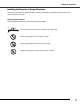
Safety Instructions Installing the Projector in Proper Directions Use the projector properly in specified positions. Improper positioning may reduce the lamp life and result in severe accident or fire hazard. Positioning Precautions Avoid positioning the projector as described below when installing. 20˚ Do not tilt the projector more than 20 degrees from side to side. 20˚ Do not point the projector up to project an image. Do not point the projector down to project an image.
Compliance Federal Communications Commission Notice This equipment has been tested and found to comply with the limits for a Class B digital device, pursuant to Part 15 of the FCC Rules. These limits are designed to provide reasonable protection against harmful interference in a residential installation. This equipment generates, uses, and can radiate radio frequency energy and, if not installed and used in accordance with the instructions, may cause harmful interference to radio communications.
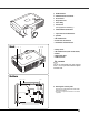
q w e r t y USB Terminal LAN Connection Terminal Zoom Lever Projection Lens Focus Ring Lens Cover (See page 60 for attaching.) u Infrared Remote Receiver i Top Controls and Indicators o Speaker !0 Air Intake Vent !1 Power Cord Connector !2 Terminals and Connectors Back !7 i !1 !2 !3 Lamp Cover !4 Air Intake Vents (back and bottom) !5 Filters !6 Adjustable Feet !7 Exhaust Vent CAUTION Hot air is exhausted from the exhaust vents. Do not put heat-sensitive objects near this side.
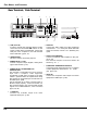
Part Names and Functions Rear Terminal / Side Terminal q w e r t y u (VARIABLE) USB SERVICE PORT COMPUTER IN 1 DVI-I COMPUTER IN 2 / COMPONENT IN R AUDIO OUT L COMPUTER / COMPONENT MONITOR OUT VIDEO IN S-VIDEO IN (MONO) AUDIO IN USB o i q USB (Series B) In order to operate the computer with the remote control and use the PAGE ed buttons on the remote control during a presentation, connect the USB port of the computer to the USB terminal with a USB cable. (pp.
Part Names and Functions Top Control q w e r t y u i POWER WARNING LAMP REPLACE TO AU UP FF -O T SE T PU IN U EN M N O CT LE SE + E M LU VO E M LU O -V o q SELECT button – Execute the selected item. (p.23) – Expand or compress the image in Digital zoom mode. (p.37) w POWER ON–OFF button Turn the projector on or off. (pp.21, 22) e MENU button y WARNING indicator Emit a red light when the projector detects abnormal condition.
Part Names and Functions q L-CLICK button Remote Control Act as the left mouse button for wireless mouse operation. (p.14) w POWER ON-OFF button Turn the projector on or off. (pp.21, 22) e SIGNAL EMISSION indicator Lights red while the laser beam is being emitted from the laser light window or a signal is being sent from the remote control to the projector. r VIDEO button q Select the VIDEO input source. (p.38) t COMPUTER button Select the COMPUTER input source. (pp.
Part Names and Functions Laser Pointer Function This remote control emits a laser beam from the laser light window. Press the LASER button to activate the laser pointer. The signal emission indicator lights red and the red laser beam is emitted. If the LASER button is pressed for more than one minute or if it is released, the laser light goes off. The laser emitted is a Class II laser. Do not look into the laser light window or point the laser beam at yourself or other people.
Part Names and Functions Wireless Mouse Operation The remote control can be used as a wireless mouse for your computer. Before operating the wireless mouse, connect your computer and the projector with the supplied USB cable. See “Connecting to a Computer” on page 17. When the Pointer function is used, the wireless mouse is not available. PRESENTATION POINTER button L-CLICK button Acts as left (click) mouse button while the projector and a computer are connected with a USB cable.
Part Names and Functions Adjustable Feet 15
Installation Positioning the Projector For projector positioning, see the figures below. The projector should be set perpendicularly to the plane of the screen. ✔Notes: •The brightness in the room has a great influence on picture quality. It is recommended to limit ambient lighting in order to obtain the best image. •All measurements are approximate and may vary from the actual sizes. 43.0' (13.1m) A:B = 9:1 (Inch Diagonal) 27.5' (8.4m) 300"(tele) 300"(wide) 18.4' (5.6m) Max. Zoom 13.8' (4.
Installation Connecting to a Computer Cables used for connection • VGA Cable (Mini D-sub 15 pin) ✽ • DVI Cable ✽ • DVI-VGA Cable • USB Cable • Audio Cables ✽ (✽ = Not supplied with this projector.) Audio Output USB port Monitor Output Monitor Output or Monitor Input External Audio Equipment Audio Input USB cable DVI cable ✽ VGA cable ✽ DVI-VGA cable Audio cable (stereo) ✽ USB COMPUTER IN 1/ DVI-I Audio cable ✽ (stereo) COMPUTER IN 2 /COMPONENT IN /MONITOR OUT This terminal is switchable.
Installation Connecting to Video Equipment Cables used for connection • Video and Audio Cable (RCA x 3) ✽ • S-VIDEO Cable ✽ • Audio Cable ✽ (✽ = Not supplied with this projector.
Installation Connecting to Component Video Equipment Cables used for connection • Audio Cables ✽ • Scart-VGA Cable ✽ • Component Cable ✽ • Component-VGA Cable ✽ (✽ = Not supplied with this projector.) Audio Output RGB Scart 21pin Output Component Video Output (Y, Pb/Cb, Pr/Cr) Component cable✽ Audio cable ✽ (stereo) External Audio Equipment Scart-VGA cable ✽ Component-VGA cable✽ Audio Input COMPUTER IN 2 /COMPONENT IN /MONITOR OUT This terminal is switchable.
Installation Connecting the AC Power Cord This projector uses nominal input voltages of 100–120 V or 200–240 V AC and it automatically selects the correct input voltage. It is designed to work with single-phase power systems having a grounded neutral conductor. To reduce the risk of electrical shock, do not plug into any other type of power system. If you are not sure of the type of power being supplied, consult your authorized dealer or service station.
Basic Operation Turning On the Projector 1 Complete peripheral connections (with a computer, VCR, etc.) before turning on the projector. 2 Connect the projector’s AC power cord into an AC outlet. The POWER indicator lights red. 3 Press the POWER ON-OFF button on the top control or on the remote control. The POWER indicator lights green and the cooling fans start to operate. The preparation display appears on the screen and the count down starts.
Basic Operation Turning Off the Projector 1 Press the POWER ON-OFF button on the top control or on the remote control, and “Power off?” appears on the screen. 2 Press the POWER ON-OFF button again to turn off the projector. The POWER indicator starts to blink red, and the cooling fans keep running. (You can select the level of fans’ quietness and speed. See “Fan” on page 54.) At this time, you can unplug the AC power cord even if the fans are still running.
Basic Operation How to Operate the On-Screen Menu The projector can be adjusted or set via the On-Screen Menu. For each adjustment and setting procedure, refer to the respective sections in this manual. TO AU T SE U + LU VO To close the On-Screen Menu, press the MENU button again. T PU IN Press the SELECT button to show the item data. Use the Point 7 8 buttons to adjust the values. POINT buttons E M LU O -V 3 MENU button CT LE SE Use the Point 7 8 buttons to select a Menu icon.
Basic Operation Menu Bar For detailed functions of each menu, see “Menu Tree” on pages 64–65. For computer source Guide Window PC System Menu Image Select Menu Screen Menu Setting Menu Show the selected Menu of the OnScreen Menu. Used to select computer system (p.30). Used to adjust size of the image [Normal/ True/Wide/Full screen/Digital zoom +/–] (pp.36–37). Used to set the projector’s operating configurations (pp.4555).
Basic Operation Sound Adjustment Direct Operation VOLUME+/buttons + E M LU VO Mute E M LU O -V Press the VOLUME+/– buttons on the top control or on the remote control to adjust the volume. The volume dialog box appears on the screen for a few seconds. CT LE SE Volume Top Control Remote Control VOL- button Press the MUTE button on the remote control to temporarily turn off the sound. To turn the sound back on, press the MUTE button again or press the VOLUME +/– buttons.
Basic Operation Top Control AUTO SET UP button POWER WARNING LAMP REPLACE TO AU UP FF -O T SE T PU IN U EN M N O CT LE SE POINT ed buttons + E M LU VO E M LU O -V Remote Control If a projected picture still has keystone distortion after pressing the AUTO SET UP button on the top control or the AUTO SET button on the remote control, correct the image manually as follows: Press the KEYSTONE button on the remote control. The Keystone dialog box appears.
Basic Operation FREEZE button Press the FREEZE button on the remote control to freeze the picture on the screen. To cancel the Freeze function, press the FREEZE button again or press any other button. AUTO PC button Press the AUTO PC button on the remote control to operate the Auto PC Adj. function. The computer screen adjustment can be done easily by pressing this button. See page 31 for details. Remote Control AUTO PC button POINT ed buttons D.ZOOM buttons FREEZE button Press the D.
Computer Input Computer System Selection This projector automatically tunes to various types of computers based on VGA, SVGA, XGA, SXGA, WXGA, or UXGA with its Multi-scan system and Auto PC Adjustment. If a computer is selected as a signal source, this projector automatically detects the signal format and tunes to project a proper image without any additional settings. (Signal formats provided in this projector are shown on pages 66-67.
Computer Input Manual PC Adjustment Some computers employ special signal formats which may not be tuned by Multi-scan system of this projector. Manual PC Adjustment enables you to precisely adjust several parameters to match those signal formats. The projector has five independent memory areas to store those parameters manually adjusted. It allows you to recall the setting for a specific computer. 1 Press the MENU button to display the On-Screen Menu.
Computer Input Display area H Use the Point 7 8 buttons to adjust the horizontal area displayed by this projector. Display area V Use the Point 7 8 buttons to adjust the vertical area displayed by this projector. Move the red frame pointer to the desired item and press the SELECT button. Reset To reset the adjusted data, select Reset and press the SELECT button. A confirmation box appears and then select [Yes]. All adjustments will return to their previous figures.
Computer Input Image Mode Selection Direct Operation Remote Control Select the desired image mode from among Dynamic, Standard, Real, Blackboard (Green), Image 1, Image 2, Image 3, and Image 4 by pressing the IMAGE button on the remote control. Dynamic For viewing pictures in a bright room. IMAGE button Dynamic Standard Real IMAGE button Blackboard(Green) Standard Normal picture mode preset on the projector. Image 1 Real Picture mode with improved halftone for graphics.
Computer Input Image Adjustment 1 Press the MENU button to display the On-Screen Menu. Use the Point 7 8 buttons to move the red frame pointer to the Image Adjust Menu icon. 2 Use the Point ed buttons to move the red frame pointer to the desired item and then press the SELECT button to display the adjustment dialog box. Use the Point 7 8 buttons to adjust the setting value. Image Adjust Menu Image Adjust Menu icon Move the red frame pointer to the desired item and then press the SELECT button.
Computer Input Store To store the adjusted data, select Store and press the SELECT button. Use the Point ed buttons to select one from Image 1 to 4 and press the SELECT button. A confirmation box appears and then select [Yes]. Stored data can be called up by selecting an “Image (1–4)” in the Image Mode Selection on page 34. Image Mode Menu Move the red frame pointer to an image item to be set and then press the SELECT button. Quit Exit the Image Adjust Menu.
Computer Input For zooming in and out the images Remote Control POINT buttons Digital zoom + Select Digital zoom +. The On-Screen Menu disappears and “D. zoom +” appears. Press the SELECT button to expand the image size. Use the Point ed7 8 buttons to pan the image. The Panning function can work only when the image is larger than the screen size. A projected image can be also expanded by pressing the D.ZOOM e button on the remote control. SELECT button D.ZOOM + button D.
Video Input Input Source Selection (Video, S-video) Direct Operation INPUT button INPUT button POWER WARNING Computer 1 (Analog) T PU IN U EN M N O FF -O Choose Video by pressing the INPUT button on the top control or the VIDEO button on the remote control. Before using these buttons, correct input source should be selected through menu operation as described below.
Video Input Input Source Selection (Component, RGB Scart 21-pin) Direct Operation INPUT button POWER WARNING Computer 1 (Analog) T PU IN U EN M N O FF -O Computer 1 (Digital) CT LE SE Choose Computer 2 by pressing the INPUT button on the top control or press the COMPUTER button on the remote control. Before using these buttons, correct input source should be selected through Menu operation as described below.
Video Input Video System Selection 1 Press the MENU button to display the On-Screen Menu. Use the Point 7 8 buttons to move the red frame pointer to the AV System Menu icon. 2 Use the Point ed buttons to move the red arrow pointer to the desired system and then press the SELECT button. Video or S-Video Auto The projector automatically detects an incoming video system, and adjusts itself to optimize its performance. When Video System is PAL-M or PAL-N, select the system manually. PAL/SECAM/NTSC/NTSC4.
Video Input Image Mode Selection Direct Operation Remote Control Dynamic Select the desired image mode from among Dynamic, Standard, Cinema, Blackboard (Green), Image 1, Image 2, Image 3, and Image 4 by pressing the IMAGE button on the remote control. Dynamic For viewing pictures in a bright room. Standard Normal picture mode preset on the projector. Cinema Picture mode adjusted with fine tone. Blackboard (Green) For the image projected on a blackboard.
Video Input Image Adjustment 1 Press the MENU button to display the On-Screen Menu. Use the Point 7 8 buttons to move the red frame pointer to the Image Adjust Menu icon. 2 Use the Point ed buttons to move the red frame pointer to the desired item and then press the SELECT button to display the adjustment dialog box. Use the Point 7 8 buttons to adjust the setting value. Contrast Image Adjust Menu Image Adjust Menu icon Move the red frame pointer to the desired item and then press the SELECT button.
Video Input Sharpness Press the Point 7 button to decrease the sharpness of the image; press the Point 8 button to increase the sharpness of the image (from 0 to 15). Gamma Use the Point 7 8 buttons to adjust the gamma value to obtain a better balance of contrast (from 0 to 15). Noise reduction Noise interference on the screen can be reduced. Select one of the following options to get smoother images. Off.......... Disabled. L1........... Lower reduction L2...........
Video Input Screen Size Adjustment This projector has the picture screen resize function, which enables you to customize the image size. 1 Press the MENU button to display the On-Screen Menu. Use the Point 7 8 buttons to move the red frame pointer to the Screen Menu icon. 2 Use the Point ed buttons to move the red frame pointer to the desired function and then press the SELECT button. Normal Provide the image at the 4:3 normal video aspect ratio. Wide Provide the image at the 16:9 wide screen ratio.
Setting Setting This projector has a Setting menu that allows you to set up the other various functions described below. 1 Press the MENU button to display the On-Screen Menu. Use the Point 7 8 buttons to move the red frame pointer to the Setting Menu icon. 2 Use the Point ed buttons to move the red frame pointer to the desired item and then press the SELECT button. The Setting dialog box appears. Setting Menu (Language) Set the red frame pointer to the item and press the SELECT button.
Setting Keystone This function is used to store or reset the keystone correction when the AC power cord is unplugged. Use the Point 7 8 buttons to switch between each option. Store ........ Keep the keystone correction even when the AC power cord is unplugged. Reset ....... Release the keystone correction when the AC power cord is unplugged. To correct keystone distortion, press the SELECT button. The “Keystone” appears on the screen. Use the Point ed buttons to correct keystone distortion (p.26).
Setting Logo (Logo and Logo PIN code lock settings) This function allows you to customize the screen logo with Logo select, Capture, and Logo PIN code lock functions. ✔Note: Logo select •When “On” is selected in the Logo PIN code lock function, Logo select and Capture functions cannot be selected. Logo select This function decides on the starting-up display from among following options. User ......... Show the image you captured Default ..... Show the factory-set logo Off............
Setting Logo PIN code lock Logo PIN code lock This function prevents an unauthorized person from changing the screen logo. Off............ The screen logo can be changed freely from the Logo Menu (p.47). On ............ The screen logo cannot be changed without a Logo PIN code. If you want to change the Logo PIN code lock setting, press the SELECT button and the Logo PIN code dialog box appears. Enter a Logo PIN code by following the steps below. The initial Logo PIN code is set to “4321” at the factory.
Setting Ceiling Ceiling When this function is set to “On,” the picture will be top/bottom and left/right reversed. This function is used to project the image from a ceiling-mounted projector. Rear When this function is set to “On,” the picture will be left/right reversed. This function is used to project the image from rear of the screen. Rear Terminal The COMPUTER IN 2 / COMPONENT IN / MONITOR OUT terminal on the back of the projector is switchable for computer input or monitor output.
Setting Standby mode This function is available when operating the projector via network. Normal ....... Supply the power to the network function even after turning off the projector. You can turn on/off the projector via network, modify network environment, and receive an e-mail about projector status while the projector is powered off. Eco ............. Select “Eco” when you do not use the projector via network. The projector’s network function will stop when turning off the projector.
Setting On start When this function is set to “On,” the projector will be automatically turned on just by connecting the AC power cord to a wall outlet. ✔Note: •Be sure to turn off the projector properly (see “Turning Off the Projector” on page 22). If the projector is turned off in the incorrect sequence, the On start function does not work properly. Lamp control This function allows you to change brightness of the screen. Normal ....Normal brightness Auto ........
Setting Security (Key lock and PIN code lock settings) Key lock This function allows you to use the Key lock and PIN code lock function to set the security for the projector operation. Key lock This function locks the top control and remote control buttons to prevent operation by unauthorized persons. ...... Unlocked. ...... Lock the operation of the top control. To unlock, use the remote control. ...... lock the operation of the remote control. To unlock, use the top control.
Setting Enter a PIN code Enter a PIN code Use the Point ed buttons to enter a number. Press the Point 8 button to fix the number and move the red frame pointer to the next box. The number changes to “✳.” If you fixed an incorrect number, use the Point 7 button to move the pointer to the number you want to correct, and then enter the correct number. Repeat this step to complete entering a four-digit number. After entering the four-digit number, move the pointer to “Set.
Setting Fan Fan This function provides the following options in the cooling fans’ operation when the projector is turned off (p.22). L1....... Normal operation L2....... Slower and lower-sound than the normal operation (L1), but it takes more time to cool the projector down. Fan control Choose the running speed of cooling fans from the following options. Normal ..... Normal speed Max.......... Faster than the normal speed.
Setting Filter counter Filter counter This function is used to set a frequency for the filter cleaning. When the projector reached a specified time between cleanings, a Filter warning icon appears on the screen, notifying the cleaning is necessary. After cleaning the filter, be sure to select RESET and set the timer. The Filter warning icon will not turn off until the filter counter is reset. Use the Point 7 8 buttons to set the timer. Select from (Off/100H/ 200H/ 300H) depending on the use environment.
Maintenance and Cleaning Warning Indicator The WARNING indicator shows the state of the function which protects the projector. Check the state of the WARNING indicator and the POWER indicator to take proper maintenance. The projector is shut down and the WARNING indicator is blinking red.
Maintenance and Cleaning Cleaning the Filter Filters prevent dust from accumulating on the optical elements inside the projector. Should the filters become clogged with dust particles, it will reduce cooling fans’ effectiveness and may result in internal heat buildup and adversely affect the life of the projector. If a “Filter warning” icon appears on the screen, clean the filters immediately. Clean the filters by following the steps below.
Maintenance and Cleaning Lamp Replacement Top Control LAMP REPLACE indicator POWER WARNING LAMP REPLACE TO AU UP FF -O T SE T PU IN N O U EN M When the projection lamp of the projector reaches its end of life, the Lamp replacement icon appears on the screen and LAMP REPLACE indicator lights yellow. Replace the lamp with a new one promptly. The timing when the LAMP REPLACE indicator should light is depending on the lamp mode.
Maintenance and Cleaning Resetting the Lamp Counter Be sure to reset the Lamp counter after the lamp is replaced. When the Lamp counter is reset, the LAMP REPLACE indicator stops lighting and the Lamp replacement icon disappears. 1 Press the MENU button to display the On-Screen Menu. Use the Point 7 8 buttons to move the red frame pointer to the Setting Menu icon. 2 Use the Point ed buttons to move the red frame pointer to Lamp counter and then press the SELECT button.
Maintenance and Cleaning Cleaning the Projection Lens Unplug the AC power cord before cleaning. Gently wipe the projection lens with a cleaning cloth that contains a small amount of non-abrasive camera lens cleaner, or use a lens cleaning paper or commercially available air blower to clean the lens. Avoid using an excessive amount of cleaner. Abrasive cleaners, solvents, or other harsh chemicals might scratch the surface of the lens.
Appendix Indicators and Projector Condition Check the indicators for projector condition. Indicators POWER WARNING LAMP REPLACE red/green red yellow Projector Condition The projector is off. (The AC power cord is unplugged.) ✽ The projector is in stand-by mode. Press the POWER ON-OFF button to turn on the projector. ✽ The projector is operating normally. ✽ The temperature inside the projector is abnormally high. The projector cannot be turned on.
Appendix Troubleshooting Before calling your dealer or service center for assistance, check the items below once again. –Make sure you have properly connected the projector to peripheral equipment as described on pages 17–19. –Make sure all equipment is connected to AC outlet and the power is turned on. –When the projector does not project an image from the connected computer, restart the computer. 62 Problem: – Solutions No power – Plug the power cord of the projector into the AC outlet.
Appendix Some displays are not seen during the operation. – Check the Display function. See page 46. PIN code dialog box appears at start-up. – PIN code lock is being set. Enter a PIN code (the “1234” or numbers you have set). See pages 21, 52–53. Computer 2 cannot be selected. – Select Computer 2 at the Terminal function. (See page 49.) The Terminal function cannot be selected. – The Terminal function cannot be selected after Computer 2 is selected.
Appendix Menu Tree Computer Input/Video Input Input Computer 1 (Analog) Go to System (1) Computer 1 (Digital) RGB (PC digital) N/A RGB (AV HDCP) N/A Quit Computer 2 RGB Go to System (1) Component Go to System (2) RGB (Scart) N/A Quit Video Auto Go to System (3) Video Go to System (3) S-video Go to System (3) Quit Wired See owner’s manual “Network Set-up and Operation” Wireless* See owner’s manual “Network Set-up and Operation” Memory Viewer* See owner’s manual of Memory viewer (op
Appendix Video Input Auto 1080i 1035i 720p 575p 480p 575i 480i Auto PAL SECAM NTSC NTSC 4.
Appendix Compatible Computer Specifications Basically this projector can accept the signal from all computers with the V-, H-Frequency mentioned below and less than 140 MHz of Dot Clock for analog signal and 110 MHz of Dot Clock for digital signal. When selecting these modes, PC adjustment can be limited.
Appendix When the input signal is digital from DVI terminal, refer to the chart below. ON-SCREEN DISPLAY D-VGA D-480p D-575p D-SVGA D-XGA D-WXGA 1 D-WXGA 2 D-WXGA 3 D-WXGA 4 D-WXGA 5 D-WXGA 6 D-WXGA 7 D-WXGA 9 RESOLUTION 640 x 480 640 x 480 768 x 575 800 x 600 1024 x 768 1366 x 768 1360 x 768 1376 x 768 1360 x 768 1366 x 768 1280 x 768 1280 x 768 1280 x 800 H-Freq. (KHz) 31.47 31.47 31.25 37.879 43.363 48.36 47.7 48.36 56.160 46.500 47.776 60.289 49.600 V-Freq. (Hz) 59.94 59.88 50.00 60.32 60.00 60.
Appendix Technical Specifications Mechanical Information Projector Type Dimensions (W x H x D) Net Weight Feet Adjustment Multi-media Projector 9.66" x 2.28" x.6.82" (294.5mm x 69.5mm x 208 mm) (Not including adjustable feet) 5.7 lbs (2.6 kg) 0˚ to 10.0˚ Panel Resolution LCD Panel System Panel Resolution Number of Pixels 0.
Appendix Accessories Owner’s Manual (CD-ROM) Quick Reference Guide AC Power Cord Remote Control and Batteries DVI-VGA Cable USB Cable Lens Cover with String PIN Code Label Network Application (CD-ROM) Soft Carrying Case USB Wireless LAN Adapter ● The specifications are subject to change without notice. ● LCD panels are manufactured to the highest possible standards. Even though 99.99% of the pixels are effective, a tiny fraction of the pixels (0.
Appendix PJ Link Notice This projector is compliant with PJLink Standard Class 1 of JBMIA (Japan Business Machine and Information System Industries Association). This projector supports all commands defined by PJLink Class 1 and is verified conformance with PJLink Standard Class 1. For PJ Link password, see page 49 on the owner’s manual “Network Set-up and Operation.
Appendix Configurations of Terminals COMPUTER IN 2 /COMPONENT IN /MONITOR OUT (ANALOG) Terminal: Analog RGB (Mini D-sub 15 pin) 4 5 10 15 2 3 9 14 8 13 7 12 1 2 3 4 5 6 7 8 1 6 11 9 10 11 12 13 14 15 Red (R/Cr) Input/Output Green (G/Y) Input/Output Blue (B/Cb) Input/Output ----Ground (Horiz.sync.) Ground (Red) Ground (Green) Ground (Blue) +5V Power Ground (Vert.sync.) Ground DDC Data Horiz. sync. Input/Output (Composite H/V sync.) Vert. sync.
Appendix PIN Code Number Memo Write down the PIN code number in the column below and keep it with this manual securely. If you forgot or lost the number and unable to operate the projector, contact the service station. Factory default set No: 1 2 3 4* Factory default set No: 4 3 2 1* *Should the four-digit number be changed, the factory set number will be invalid. Put the label below (supplied) on in a prominent place of the projector's body while it is locked with a PIN code.
KW6AC SANYO Electric Co., Ltd.