
Installation guide

D300914X012 9/96
EFisher Controls International, Inc. 1996; All Rights Reserved
Fisher and Fisher-Rosemount are marks owned by Fisher Controls International, Inc. or Fisher-Rosemount Systems, Inc.
All other marks are the property of their respective owners.
Use these instructions when inspecting or replacing
standard PTFE packing.
WARNING
Avoid personal injury or property dam-
age from sudden release of process
pressure or bursting of parts. Before
performing any maintenance opera-
tions:
D Disconnect any operating lines
providing air pressure, electric power,
or a control signal to the actuator. Be
sure the actuator cannot suddenly open
or close the valve.
D Use bypass valves or completely
shut off the process to isolate the valve
from process pressure. Relieve process
pressure from both sides of the valve.
Drain the process media from both
sides of the valve.
D Vent the pneumatic actuator load-
ing pressure and relieve any actuator
spring precompression.
D Use lock-out procedures to be sure
that the above measures stay in effect
while you work on the equipment.
If you are installing the system in a valve that is still
connected to an actuator, remove the actuator from
the valve to provide sufficient space to install the
packing assembly. If a spring-return actuator is used,
it is possible that disconnecting the stem connector
will allow the spring to force the actuator to the end of
its travel. Be sure the actuator spring is resting on its
travel stop. Refer to the appropriate valve and actua-
tor instruction manuals to remove the actuator.
1. Remove the packing flange nuts, packing flange,
and bushing (keys 212, 201, and 208). Carefully push
out all the remaining packing box parts from the bon-
net using a rounded rod or other tool that will not
scratch the packing box wall or lower guide bushing.
Clean the packing box and the metal packing box
parts.
2. Inspect the valve stem threads and packing box
surfaces for any sharp edges that might cut the pack-
ing. Scratches or burrs could cause packing box leak-
age or damage to the new packing. If the surface
condition cannot be improved by light sanding, re-
place the damaged parts.
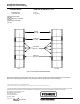
3. Install new packing and the metal packing box
parts according to the appropriate arrangement in fig-
ure 1. Place a smooth-edged pipe over the valve
stem, and gently tap each soft packing part into the
packing box, being sure that air is not trapped be-
tween adjacent soft parts.
4. Slide the bushing and packing flange (keys 208
and 201) into position. Lubricate the packing flange
studs (key 200) and the faces of the packing flange
nuts (key 212). Replace the packing flange nuts, but
do not tighten.
5. For PTFE packing, tighten the packing flange nuts
alternately in small equal increments until one of the
nuts reaches the minimum recommended torque
shown in table 1. Then, tighten the remaining flange
nuts until the packing flange is level and at a 90-de-
gree angle to the valve stem.
6. Mount the actuator on the valve assembly, and
reconnect the actuator and valve stem. Refer to the
appropriate valve and actuator instruction manuals
when connecting the valve to the actuator. Check for
leakage around the packing follower when the valve is
being put into service. Retighten the packing flange
nuts as required.
For additional information concerning the installation
of this packing kit, please consult the appropriate
Fisher Controls product instruction manual.
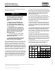
Table 1. Recommended Torque for Packing Flange Nuts
VALVE
SIZE
VALVE
STEM
DIAMETER
ANSI
PTFE TYPE PACKING
SIZE,
INCHES
Inch mm
ANSI
CLASS
Minimum
Torque
Maximum
Torque
Inch
mm
LbfSin NSm LbfSin NSm
1, 1-1/2,
1/2
12 7
150 15 1.7 23 2.6
1
,
1 1/2
,
2
1/2 12.7
300 20 2.3 31 3.5
3
1
25 4
150 21 2.4 32 3.6
3 1 25.4
300 29 3.3 43 4.9
4
1 1/4
31 8
150 15 1.7 22 2.5
4 1-1/4 31.8
300 20 2.3 30 3.4
Installation Instructions
Design CP PTFE Packing