RC4Q/U (TLS-9960 GB) Mon. Aug., 23/1999 INSTRUCTION MANUAL TLS-9960 Time Lapse Video Cassette Recorder English Magnétoscope time lapse à cassette Français Videograbador en lapsos de tiempo Español Please read this manual and accompanying “IMPORTANT SAFETY INSTRUCTIONS” sheet carefully before connecting your VCR and operating it for the first time. Be sure to read carefully and follow all the PRECAUTIONS on page 1. Keep the manual in a safe place for future reference.
RC4Q/U (TLS-9960 GB) Mon. Aug., 23/1999 PRECAUTIONS The lightning flash with arrowhead symbol, within an equilateral triangle, is intended to alert the user to the presence of uninsulated “dangerous voltage” within the product’s enclosure that may be of sufficient magnitude to constitute a risk of electric shock to persons.
RC4Q/U (TLS-9960 GB) Mon. Aug.
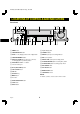
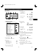
RC4Q/U (TLS-9960 GB) Mon. Aug., 23/1999 LOCATIONS OF CONTROLS AND INDICATORS Front Panel 12 3 4 5 6 7 8 9F REC/PLAY l SPEED j » l « COUNTER RESET MEMORY STILL PAUSE ON ALARM SPEED DURATION 2H 20S 12H PROG.
RC4Q/U (TLS-9960 GB) Mon. Aug., 23/1999 LOCATIONS OF CONTROLS AND INDICATORS 5 Mode display Digital Display 1 2 3 4 œ Recording/playback speed mode 5 œ Alarm search mode œ Alarm scan mode OFF E M H G F9 8 M œ Dew display S 7 6 1 Operation Indicators 5, 6 Mode display œ They display the actual operation mode.
RC4Q/U (TLS-9960 GB) Mon. Aug.
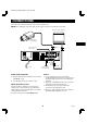
RC4Q/U (TLS-9960 GB) Mon. Aug., 23/1999 CONNECTIONS Connect the video camera and monitor TV as shown in the figure below. NOTE: Before making the connections, make sure the devices are disconnected from the power outlet.
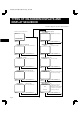
RC4Q/U (TLS-9960 GB) Mon. Aug., 23/1999 TYPES OF ON-SCREEN DISPLAYS AND DISPLAY SEQUENCE Reference pages are shown in square brackets.
RC4Q/U (TLS-9960 GB) Mon. Aug., 23/1999 TYPES OF ON-SCREEN DISPLAYS AND DISPLAY SEQUENCE NOTES: Using the JOG dial and SHUTTLE ring œ When a menu is displayed, recording will not be possible. JOG dial œ Press the SEARCH/AUDIO ON or MENU button, the setting procedure is now completed. œ Put the tip of your index finger into the depression then turn the dial in any direction. œ During recording or playback the menus cannot be displayed.
RC4Q/U (TLS-9960 GB) Mon. Aug., 23/1999 SETTING THE LANGUAGE AND CLOCK 5 Turn the SHUTTLE ring to set the month the daylight Language Setting saving time adjustment is made, then turn the JOG dial clockwise. English, French or Spanish can be selected by the user. 1 Turn the power on to all devices used. 2 Press the MENU button to display the (SET UP 1) 01, 02,.....11, 12 (for January, February......November, December) 6 Turn the SHUTTLE ring to set the time the daylight menu.
RC4Q/U (TLS-9960 GB) Mon. Aug., 23/1999 CHANGING THE ON-SCREEN DISPLAY Selecting the On-screen Display Changing the Date/Time Display Position You can select to display or not the date, time, the number of alarm recordings and tape speed. 1 Turn the power on to all input devices to the VCR. 2 Set the ON SCREEN switch to the “ON” position. 1 Turn the power on to all devices used. 2 Press the MENU button until the (SET UP 2) menu is ø The date and time are displayed.
RC4Q/U (TLS-9960 GB) Mon. Aug., 23/1999 VIDEO CASSETTE TAPES Use only video cassette tapes bearing the w logo. This VCR was primarily designed for use with T-120 cassette tapes, it is recommended to use T-120 standard grade VHS video cassette tapes for optimal performance. Loading 1 Place the cassette, label side up, in the loading slot. Gently push the center of the cassette until it is loaded automatically.
RC4Q/U (TLS-9960 GB) Mon. Aug., 23/1999 VIDEO CASSETTE TAPES Correct tape thread check function Setting the Action to Take When a Cassette is Loaded If the correct tape thread check function is on, after the cassette tape is loaded, a mechanism will operate for about 5 seconds to check that the tape has been threaded (loaded) correctly and the cassette indicator “o” will blink during that period. If the tape is not loaded properly, the cassette will be ejected.
RC4Q/U (TLS-9960 GB) Mon. Aug., 23/1999 TAPE MANAGEMENT FUNCTION After the tape management data is checked, if there is no conflict, recording starts and the data at the beginning of the tape is updated. The message “T. MANAGE. OK” is displayed on-screen while the data is updated. This VCR is equipped with a tape management function.
RC4Q/U (TLS-9960 GB) Mon. Aug., 23/1999 TAPE MANAGEMENT FUNCTION 6 Turn the SHUTTLE ring, to select the desired number Setting the Tape Management Function of re-recording times. 1 Press the MENU button until the (TAPE OFF . . . . The number of re-recording times will not be checked. MANAGEMENT) menu is displayed. ø The “TAPE MANAGE.” setting is flashing. 1-100 . . . Maximum number of re-recording times. @@@@ öTAPE@MANAGE.
RC4Q/U (TLS-9960 GB) Mon. Aug., 23/1999 TAPE MANAGEMENT FUNCTION PROTECT DAY CONFLICT Tape Management Conflict Display The tape is protected, the tape protection term (ex. 30 days) is not yet over. If when the tape management function checks the tape data a conflict that prevents recording is found, the (TAPE MANAGEMENT) menu is displayed with the conflicting setting flashing and the VCR go into the stop mode. If in the (SET UP 2) menu, in the BUZZER section WARNING is set to “Y”, the buzzer is heard.
RC4Q/U (TLS-9960 GB) Mon. Aug., 23/1999 NORMAL RECORDING [Recording Speed Mode] Normal Recording Maximum Recording recording speed mode duration (with a (hour mode) T-120 cassette tape) (hours) 2 2 12 14 24 26 48 50 72 74 96 98 120 122 168 170 240 242 360 362 480 482 720 722 960 962 000 — Before starting œ Turn the power on to all devices used. œ Load a cassette tape with erasure-prevention tab.
RC4Q/U (TLS-9960 GB) Mon. Aug., 23/1999 NORMAL RECORDING Concerning the Number of Times Tapes can be Rerecorded on Changes to the Recording Speed Mode During Recording Depending on the recording speed mode, the tape must be replaced after a certain number of recording times. It is possible to permit or prevent changing the recording speed mode during recording. Refer to the table below for the maximum number of times a tape can be recorded on.
RC4Q/U (TLS-9960 GB) Mon. Aug., 23/1999 NORMAL RECORDING Recording Check The image being recorded can be checked. 1 During recording, press the PLAY (REC CHECK) button. ø The tape will be rewound and then played back. The VCR will then return to the previous recording mode. NOTE: œ During recording check operations, recording is suspended momentarily. Clog Detection This VCR is equipped with a clog detection function. The recording quality is monitored automatically.
RC4Q/U (TLS-9960 GB) Mon. Aug., 23/1999 AUTOREPEAT RECORDING Autorepeat Recording Setting the Mode at the End of the Tape The same tape can be recorded over many times. œ Follow the Before starting steps, under “NORMAL RECORDING”. In the (SET UP 3) menu, you can set the mode of the VCR mode when the tape reaches the end during recording. 1 Set the REPEAT REC switch to the “ON” position. 1 Press the MENU button until the (SET UP 3) menu is displayed. ø The REPEAT indicator will light.
RC4Q/U (TLS-9960 GB) Mon. Aug., 23/1999 ALARM RECORDING If the ALARM DURATION switch is set to the “PROG.” position, please continue with steps 5 and 6. By connecting the ALARM IN terminal to a door switch, an interphone, etc., a recording can be done only when necessary. 5 Turn the JOG dial, until the “ALARM DURATION” setting is flashing.
RC4Q/U (TLS-9960 GB) Mon. Aug., 23/1999 ALARM RECORDING Alarm Recording Counter Display Checking the Alarm Recordings Time œ During alarm recording, “AL” will be flashing on the digital display. 1 Press the MENU button until the (ALARM TIME) menu is displayed. œ If the ON SCREEN switch is set to the “ON” position, the number of alarms will flash on the monitor screen. ø The number of alarm recordings, and the 8 most recent alarm recording times are displayed.
RC4Q/U (TLS-9960 GB) Mon. Aug., 23/1999 ALARM RECORDING Alarm Search Alarm Scan To go to the beginning of a desired alarm recording. To look for an alarm recording by viewing the first 5 seconds of each alarm recording. 1 Press the SEARCH/AUDIO ON button during stop 1 Press the SEARCH/AUDIO ON button twice during mode. stop mode. ø “AL SEARCH 01” will be displayed on screen. ø “AL SCAN” will be displayed on screen.
RC4Q/U (TLS-9960 GB) Mon. Aug., 23/1999 PROGRAM TIMER RECORDING 7 Turn the SHUTTLE ring to set the recording stop There are two program timer recording methods, daily recording or recording on certain days of the week. minutes (ex: 00), then turn the JOG dial clockwise. Example 1: To record on every Saturday from 9:00 ø The “SPD” (recording speed) position will start flashing. AM to 5:00 PM (17:00), in 24-hour mode (recording speed).
RC4Q/U (TLS-9960 GB) Mon. Aug., 23/1999 PROGRAM TIMER RECORDING 8 Turn the SHUTTLE ring, to set the desired stop day A timer recording of more than 24 hours can only be set on the 7th (SAT) and 8th (DLY) lines of the (TIMER SET) menu. of the week (ex: MON), then turn the JOG dial clockwise. ø The recording stop hour position starts flashing.
RC4Q/U (TLS-9960 GB) Mon. Aug., 23/1999 PROGRAM TIMER RECORDING Setting the Holidays Changing a Program Timer Recording By setting the holidays, timer recording will be conducted on those days, as set for Sundays. 1 Press the MENU button until the (TIMER SET) menu 1 Press the MENU button until the (HOLIDAY SET) 2 Turn the JOG dial, until the setting to correct is is displayed. menu is displayed. flashing. 3 Turn the SHUTTLE ring, to correct the setting.
RC4Q/U (TLS-9960 GB) Mon. Aug., 23/1999 PROGRAM TIMER RECORDING NOTES: œ During timer recording or timer recording stand-by, all the buttons on the VCR, except the TIMER button and the buttons to set/cancel the security lock (see page 34), are disabled. œ If the power fails, the recording will be interrupted. When the power is restored, the recording will resume if the stop time has not yet been reached, and “P” will be displayed on the digital display.
RC4Q/U (TLS-9960 GB) Mon. Aug., 23/1999 RECORDING USING AN EXTERNAL TIMER INPUT 5 Follow steps F and G under “PROGRAM TIMER Recording can be controlled by an external start/stop signal input at the EXT TIMER IN terminal. RECORDING on page 23”. ø When an external signal is input, “E” will light on the digital display and recording will take place. Example 3: To record using the signal input at the EXT TIMER IN terminal, in 24-hour mode.
RC4Q/U (TLS-9960 GB) Mon. Aug., 23/1999 SERIES RECORDING The SERIES OUT signal will be presence either at the point when the counter reading is 1H57M00S or when VCR No. 1 reaches the end of the tape, whichever is first. The signal will stop 70 seconds after the tape end point of VCR No. 1. Using 2 VCRs or more, the series recording function lets you switch recording from one unit to the next (only with VCRs of the same model as this one). Series Recording Setup When this signal is received by VCR No.
RC4Q/U (TLS-9960 GB) Mon. Aug., 23/1999 SERIES RECORDING 3 Press the REC button on VCR No.1. Continous Loop Recording Setup It is possible to configure at least two this VCR for continous loop recording. ø Recording will start in series recording mode. 4 Set the security lock on VCR No.1. Under loop recording when the recording finishes on the first unit, the new recording will start on the second unit. When the recording finishes on the second unit, recording will start on the first unit.
SINGLE IMAGE RECORDING The single image recording function of this VCR can be used to create image data files or animations. Single Image Recording Setup 1 In stop mode, press the REC/PLAY SPEED l (or j) button, to set the recording speed to “0 00”. 2 Press the MENU button until the (SET UP 4) menu is displayed.
RC4Q/U (TLS-9960 GB) Mon. Aug., 23/1999 NORMAL PLAYBACK Normal Playback Tracking Control 1 Turn on the power to the VCR and TV monitor. 2 Load the video cassette tape. 3 Press the REC/PLAY SPEED l (or j) button to If there is noise in the image during playback, 1 While looking at the playback picture, press and hold the TRACKING/V. STILL+ button to minimize the noise. select the playback speed mode. 2 If it cannot be minimized, press the TRACKING/V.
RC4Q/U (TLS-9960 GB) Mon. Aug., 23/1999 SPECIAL PLAYBACK Picture Search (Forward and Reverse) Reverse Playback 1 Turn the SHUTTLE ring clockwise (or 1 Turn the SHUTTLE ring counterclockwise and hold it, counterclockwise), during normal playback. See “SHUTTLE Ring Operation”. ø The image can be seen while the tape is advanced (or rewound) at high speed. 2 To return to normal playback, release the SHUTTLE during normal playback. See “SHUTTLE Ring Operation”. ø Reverse playback will start.
RC4Q/U (TLS-9960 GB) Mon. Aug., 23/1999 SPECIAL PLAYBACK Day/Time Search SHUTTLE Ring Operation 1 Press the SEARCH/AUDIO ON button three times From normal playback, still image, stop mode, etc., turn the clockwise or counterclockwise to select a mode as indicated below. during stop mode. ø “T/D SEARCH 01 00:00” will be displayed on screen. Day 2 1 Turn the SHUTTLE ring in either direction where the desired mode is selected.
TAPE COUNTER Using the counter, it is easy to find a desired recording. 1 Press the COUNTER RESET button, at the beginning of the desired recording. ø The counter will be reset to “0H 00M 00S”. 2 Press the COUNTER MEMORY button.
RC4Q/U (TLS-9960 GB) Mon. Aug., 23/1999 SETTING THE BUZZER During alarm recording, if the tape reaches the end, if buttons are pressed, or if there is a VCR mechanical failure, the tape will stop or be ejected and a buzzer can be sounded. KEY IN . . . . . The buzzer will be heard when one of the VCR buttons is pressed or when the JOG dial or the SHUTTLE ring is turned. 1 Press the MENU button until the (SET UP 2) menu is WARNING . .
SETTING THE RS-232C OR RS-485 DATA TRANSFER SPEED The VCR can be controlled by a computer connected to the RS-232C connector. It can also be controlled through a special controller connected to the RS-485 connector. You must specify which connector (RS-232C or RS-485) is used. (Refer to “Data Transfer Speed Setup.”) Data Transfer Speed Setup 1 Press the MENU button until the (SET UP 3) menu is displayed. @@@@@@@ öALARM@MODE@@@@@@@Y1 öALARM@DURATION@@@20S öEXT@TIME@ADJ.
RC4Q/U (TLS-9960 GB) Mon. Aug., 23/1999 SETTING THE RS-232C OR RS-485 DATA TRANSFER SPEED RS485 RJ-11 connector layout RS-485 Connection This VCR can use the straight type or crossed type connecting cables. 1 If using a straight type cable, connect it from the “A” to the “A” or from the “B” to the “B” RS-485 connector. 6 NOTE: Do not connect to phone line.
RC4Q/U (TLS-9960 GB) Mon. Aug., 23/1999 OUTPUT TERMINALS TAPE END OUT Terminal WARNING OUT Terminal œ During recording, when the end of the tape is reached or when the tape counter reading indicates 1 hours 57 minutes or more, the output becomes 0V (Low). œ If the tape stops or other problem, the output becomes 0V (Low). œ To reset the output, press the STOP or ALL RESET button or unplug the power cord then plug it back in. œ To reset the output, press the STOP or EJECT button.
OUTPUT TERMINALS SW OUT Terminal When recording, a pulse signal is output at the SW OUT terminal. This terminal is usually connected to the switch input (SW IN) of devices like a camera switcher unit, or a quad compressor. SW OUT Terminal Output Setting 1 Press the MENU button until the (SET UP 4) menu is displayed. ø The FIELD (or FRAME) setting is flashing.
RC4Q/U (TLS-9960 GB) Mon. Aug., 23/1999 OUTPUT TERMINALS REMOTE Jack Remote control setting You can use a VA-RMN01 Remote Control Unit (sold separately) to control remotely the VCR. The remote control switch 7 can be set to either eject the tape or access the menus. NOTE: 1 Press the MENU button until the (SET UP 1) menu is displayed. œ The functions not available on the VCR will not operate.
RC4Q/U (TLS-9960 GB) Mon. Aug., 23/1999 HEADS SWITCHING FUNCTION This unit is equipped with 4 double azimuth heads. Under normal conditions, recording and playback is done using the main heads “A1” and “B1”. B2 (secondary) Azimuth indicator A1 (main) SC NOTES: B1 (main) œ When the end of the tape is reached, the heads combination automatically returns to the normal setting.
RC4Q/U (TLS-9960 GB) Mon. Aug., 23/1999 MAINTENANCE Daily Inspection Periodic Inspection The following daily inspections are recommended in order to assure long-term and trouble-free operation of the unit. Periodic inspection and maintenance should be referred to your dealer. The daily inspections are particularly important if using autorepeat recording.
RC4Q/U (TLS-9960 GB) Mon. Aug., 23/1999 MAINTENANCE Maintaining and Checking The Mechanism To maintain the VCR functions and features working properly, and to avoid damages or dirt on the tape, it is recommended to follow the maintenance points and periodicity indicated below. For detailed information, please contact your dealer.
RC4Q/U (TLS-9960 GB) Mon. Aug., 23/1999 TROUBLESHOOTING GUIDE If the unit does not operate normally when you follow the instructions indicated in the manual, please refer to the table below.
RC4Q/U (TLS-9960 GB) Mon. Aug., 23/1999 SPECIFICATIONS General Specifications Video heads system Audio recording Tape speed Specified video cassette tape Recording/playback time Fast forward/rewind time Television system RS-232C/RS-485 data transfer speed Dual-azimuth 4-head rotating helical scanning system: Dual azimuth 2-head for record and standard playback Dual azimuth 4-head for forward picture search, reverse picture search and still mode In 2-, 12- and 24-hour modes 33.
RC4Q/U (TLS-9960 GB) Mon. Aug., 23/1999 SANYO INDUSTRIAL VCR WARRANTY OBLIGATIONS In order to obtain warranty service, the product must be delivered to and picked up from an Authorized Sanyo Service Center at the user’s expense, unless specifically stated otherwise in this warranty. The names and addresses of Authorized Sanyo Service Centers may be obtained by calling the toll-free number listed below.
RC4Q/U (TLS-9960 E) Wed. June, 06/2001 SANYO Electric Co., Ltd. 1AC6P1P1879– –D RC4Q/U (0601KP-01) Issue No. 5 Copyright SANYO, 1999 All rights reserved.