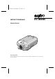
L5AB2/US (VCC-WB2000) GB 2002, 6, 25 INSTRUCTION MANUAL VCC-WB2000 Network Camera About this manual Before installing and using this unit, please read this manual carefully. Be sure to keep it handy for later reference.
L5AB2/US (VCC-WB2000) GB 2002, 7, 4 Contents Information to user........................................... 2 Precautions ....................................................... 3 Alarm Setting...................................................35 External Alarm Sensor Settings............35 MOTION DETECTOR SET Settings .......37 Features ............................................................ 4 Alarm Data Recording Capacity............38 Accessories ................................................
L5AB2/US (VCC-WB2000) GB 2002, 7, 4 Information to user Safety Guard This equipment has been tested and found to comply with the limits for a Class B digital device, pursuant to Part 15 of the FCC Rules. These limits are designed to provide reasonable protection against harmful interference in a residential installation.
L5AB2/US (VCC-WB2000) GB 2002, 7, 4 Precautions In case of problem Do not use the camera if smoke or a strange odour comes from the unit, or if it seems not to function correctly. Disconnect the power cord immediately, and consult your dealer (or a Sanyo Authorized Service Centre). Cleaning • Dirt can be removed from the cabinet by • Do not open or modify Do not open the cabinet, as it may be dangerous and cause damage to the unit.
L5AB2/US (VCC-WB2000) GB 2002, 7, 4 Features Operating environment Web Server Function This camera is equipped with a web server function. The camera can be accessed using a computer’s web browser in order to view the camera images. In addition, up to a maximum of 16 users can simultaneously access a single camera on the network.
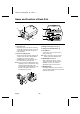
L5AB2/US (VCC-WB2000) GB 2002, 7, 4 Name and Function of Each Part 4 5 3 PC CARD MONITOR OUT 1 RS-232C ETHERNET 6 COM AC24V OUT DC12V GND PC 3 7 2 1 Lens mount cap MODEM ALARM IN CLASS 2 WIRING 3 Flange back locking screws (p. 8) Attach this cap to protect the lens mounting section. When using the camera, remove the cap and attach the automatic iris-type lens (sold separately). 4 Flange back adjustment dial (p.
L5AB2/US (VCC-WB2000) GB 2002, 7, 4 Name and Function of Each Part I PC CARD MONITOR OUT 8 RS-232C ETHERNET H G COM AC24V OUT DC12V GND PC POWER 1 2 MODEM ALARM IN J 9 8 Link indicator CLASS 2 WIRING F G RS-232C connector This indicator illuminates when the camera is connected to a network. It flashes while data transmission is in progress. Use this connector to connect the camera to a modem for transmission of data along telephone lines, or for connecting the camera to a computer.
L5AB2/US (VCC-WB2000) GB 2002, 7, 4 Attaching the Lens Use a DC-type automatic iris-type lens (sold separately). 1 Remove the lens mount cap. 3 Connect the lens iris plug to the lens iris output connector of the camera. Lenses from other manufacturers may have different plug shapes and specifications. In such cases, you may need to rewire the lens iris plug. 1 (–) control coil 2 (+) control coil 2 Attach the CS mount-type lens. Note: The “L” part of the lens should be 5 mm or less in length.
L5AB2/US (VCC-WB2000) GB 2002, 7, 4 Flange Back Adjustment The flange back is the distance between the lens (sold separately) and the image capturing surface of the camera. It is adjusted at the time of shipment from the factory to accommodate the types of lenses that are generally assumed to be in use. Accordingly, the flange back does not normally need to be adjusted.
L5AB2/US (VCC-WB2000) GB 2002, 7, 4 Connections Turn off the power for all equipment before making any connections. Basic Connections 1 Connect the camera to a computer. Connect a cable between the ETHERNET connectors of the camera and the computer. Use a crossed wire-type Ethernet cable. 2 Connect the power supply. When using this unit, the supplied clamping core A must be installed on the power cord, in order to prevent electromagnetic interference to the other devices connected.
L5AB2/US (VCC-WB2000) GB 2002, 7, 4 Connections Connecting to a LAN Connecting to a Wireless LAN Use an Ethernet cable to connect the ETHERNET connector of the camera to the LAN’s Ethernet switching hub. ☞ Use a straight-type Ethernet cable. This camera can be connected to wired LANs using an Ethernet cable, and it can be connected to wireless LANS. ☞ To connect the camera to a wireless LAN, insert a wireless LAN card into the PC CARD slot of the camera.
Connections PPP (Dial-up) Connections If connecting the camera using PPP, you will need to install the Network Archiving software (sold separately). In addition, the data that is transmitted via PPP connections consists of alarm images and alarm information. In addition to the connection method shown below, you can also connect the camera to an ISDN terminal adapter and use the Network Archiving software. Refer to the documentation provided with the Network Archiving software for further details.
L5AB2/US (VCC-WB2000) GB 2002, 7, 4 Network Camera Settings In order to use the camera as a network camera, you must make the following settings in the order given. When making network connection settings, the network settings must always be made first. 1 Installation of Plug-in Software (p. 13) Use the accessory setup CD-ROM to set u the computer. 2 Computer and Camera Settings (p. 16) Connect the computer and the camera directly, and access the camera using the computer’s web browser.
L5AB2/US (VCC-WB2000) GB 2002, 7, 4 Network Camera Settings 1 Installation of Plug-in Software Install the plug-in software (on the setup CD-ROM) onto the computer that is to be used. Installing the plug-in software makes it possible to view live images from network cameras using the computer’s web browser. 1 Turn on the power for the computer. 6 Click the [Next] button. After Windows has loaded, continue to the next step. 2 Insert the setup CD-ROM into the CD-ROM drive of the computer.
L5AB2/US (VCC-WB2000) GB 2002, 7, 4 Network Camera Settings 8 Type in your username and organization 10 name, and then click the [Next] button. Click the [Finish] button. This completes the installation of the plug-in software. 9 Click the [Install] button. Installation of the software will start and the window display will change to show the installation progress.
L5AB2/US (VCC-WB2000) GB 2002, 7, 4 Network Camera Settings Browser Settings Check that the Security settings for Microsoft Internet Explorer are set as described below. Select Internet Options from the Tools menu, click the Security tab and then click the Custom Level button to display the settings. Cookie Settings The camera uses cookies. If using Internet Explorer Version 6.
L5AB2/US (VCC-WB2000) GB 2002, 7, 4 Network Camera Settings 2 Computer and Camera Settings Once the plug-in software has been installed, use the computer’s web browser to access the camera. Note: The network camera handles large volumes of image data that has been compressed into JPEG2000 format. In order to provide smooth access to the camera, you should close any other applications that you do not need to have open.
L5AB2/US (VCC-WB2000) GB 2002, 7, 4 Network Camera Settings 3 Network Connection Settings 1 Select the desired language (e.g. English) in the language selection window, and then click the [SET] button. The main menu window will be displayed. Available languages: English, French, German, Spanish (Closing the initial window) To change the language or stop tasks such as live image monitoring, click the network disconnect button.
L5AB2/US (VCC-WB2000) GB 2002, 7, 4 Network Camera Settings A NETWORK SET Settings These settings are used in order to connect the camera to the network. Note: Check with the network system administrator for details on settings related to the network itself, such as IP address settings. Default settings displayed Reset if necessary 1 2 3 4 1 Click the [NETWORK] button in the main 2 Set the password. menu.
L5AB2/US (VCC-WB2000) GB 2002, 7, 4 Network Camera Settings 1 Changing a password Example: To change the password for the Administrator level (ID3) to “ 1234” Passwords can consist of between 4 and 8 numerals. ☞ Type “1234” as the password in the password column for ID3, and then click the [SET] button. A pop-up menu will be displayed. Click the [OK] button. The following screen will then be displayed. Check that the details are correct, and then close the window.
L5AB2/US (VCC-WB2000) GB 2002, 7, 4 Network Camera Settings B WIRELESS LAN SET Settings These settings are used in order to connect the camera to an access point for a wireless LAN. ✱ 1 2 3 4 5 1 Insert a wireless LAN card (sold 4 Change the following settings if required. separately) into the PC CARD slot. (p. 10) 1 CURRENT CHANNEL 2 Click the [WIRELESS LAN] button in the This shows the frequency channel for the access point that is to be used to connect to. main menu.
L5AB2/US (VCC-WB2000) GB 2002, 7, 4 Network Camera Settings 3 WEP ENCIPHERMENT 5 Ask the network administrator for the This is a security function that encrypts the data being transmitted so that it cannot be intercepted by an unauthorized third party. The default setting is “DISABLE”. To enable encryption, select the number of bits for the encryption key to use from the drop-down list box. Available settings: • WEP40: The encryption key can consist of up to 5 alphanumeric characters.
L5AB2/US (VCC-WB2000) GB 2002, 7, 4 Network Camera Settings C PPP SET Settings These settings are used in order to connect the camera to the Internet via a modem. Note: When using modem connections, you cannot access the camera using a computer’s web browser. You should normally connect the camera to a wired LAN or wireless LAN. Must be entered 1 2 Must be entered 3 4 5 6 8 7 1 Install the Network Archiving software 5 Type in the telephone number, login ID (sold separately) to the computer.
L5AB2/US (VCC-WB2000) GB 2002, 7, 4 Network Camera Settings 1 AUTHENTICATION 7 AUTO IP ADDRESS display This sets the verification protocol to be use when connecting to the access point. Set this to the protocol specified by the Internet Service Provider. It should normally be set to “AUTO”. This shows the IP address for the camera. Note: This is only displayed while the camera is connected. 8 ERROR INFO.
L5AB2/US (VCC-WB2000) GB 2002, 7, 4 Menu Screen and Main Menu • The menu screen is first displayed when the network camera and computer settings have been • completed and the language selection is being made. The initial menu screen shows live images. The main menu can be used to select items that require settings, to select the image quality for live images, and to disconnect the camera from the network.
L5AB2/US (VCC-WB2000) GB 2002, 7, 4 Menu Screen and Main Menu • [STATUS] button (p. 44) 2 Menu select buttons When you click on one of these buttons, the menu screen changes to the screen corresponding to that button, and you can use the screens to change the camera settings and other setting such as for the network. • [LIVE VIEW] button (p. 28) This button lets you monitor camera images. The live image screen is the initial menu screen that is displayed.
L5AB2/US (VCC-WB2000) GB 2002, 7, 4 Viewing Camera Images ID1 ID2 ID3 You can view the images from a camera by starting up the computer’s web browser and using it to access the camera’s network address. Opening and Closing the Initial Screen 1 Start the web browser on the computer. 2 Type the IP address (http://...) into the location bar of the web browser, and then press the [Enter] key. The password entry window will be displayed. Note: Type in the IP address that was set in “Network Settings”. (p.
L5AB2/US (VCC-WB2000) GB 2002, 7, 4 Viewing Camera Images 4 Select the language and then click the [SET] button. The main menu screen will be displayed. 5 When you have finished, click the network disconnect button.
L5AB2/US (VCC-WB2000) GB 2002, 7, 4 LIVE VIEW Settings ID1 ID2 Click the [LIVE VIEW] button in the main menu. The live image screen will be displayed. The live image screen lets you make settings such as alarm data detection and recording status, and also for the image quality, compression ratio, image size and enlargement ratio for the images that are being transmitted. If selecting setting values for items from the drop-down list boxes, be sure to click the [SET] button after making a selection.
LIVE VIEW Settings 2 Live image transmission settings C RESOLUTION setting Select the required setting from the respective drop-down list boxes, and then click the [SET] button. A FRAME RATE setting This lets you set the image transmission speed to one of five settings. Images can be transmitted at maximum speed depending on the network environment that the camera is connected to. The default setting is “STEP 5”.
L5AB2/US (VCC-WB2000) GB 2002, 7, 4 LIVE VIEW Settings E IMAGE MODE setting Saving Images into a Computer The camera images that are being monitored can be saved a still images in the computer’s storage area in JPEG2000 format. This lets you set whether live images are displayed in color or black and white. The default setting is color mode (COLOR). To change the mode to black and white, select “GRAY”.
L5AB2/US (VCC-WB2000) GB 2002, 7, 4 VIEW FRAME Operations Click the [VIEW FRAME] button in the main menu. The menu select buttons will disappear and only the image in the live image screen will be displayed. 1 2 1 [BACK] button Click to return to the previous screen. 2 Network disconnect button Click to disconnect from the network. Note: The resolution for the VIEW FRAME screen will be fixed at 720 x 480 regardless of the RESOLUTION setting.
CAMERA Settings This lets you set the camera title and adjust the images in accordance with the camera setting-up conditions. Click the [CAMERA] button in the main menu. The CAMERA SET screen will be displayed.
L5AB2/US (VCC-WB2000) GB 2002, 7, 4 CAMERA Settings 5 BRIGHT ☞ Setting manual white balance (MANUAL) This lets you set the image brightness to one of five settings. Click the and buttons repeatedly to adjust the settings for R (red) and B (blue). Setting range: 1 to 5 (Default: 3) Setting range: 0 to 255 Note: The red or blue component becomes stronger when the setting is higher. Note: The larger the setting, the brighter are the images.
L5AB2/US (VCC-WB2000) GB 2002, 7, 4 CAMERA Settings Setting the camera title 1 Move the cursor to the current camera title (e.g. NET_CAM), and delete the title. 2 Type in the new camera title (e.g. CAM_1). The camera title can be up to eight characters in length, and may include alphanumeric characters and the underscore character only. 3 Click the [SET] button. The new camera title will be saved and it will appear in the camera title display of the live image screen.
L5AB2/US (VCC-WB2000) GB 2002, 7, 4 Alarm Setting ID3 The camera is equipped with two types of alarm function: an external alarm sensor and a motion sensor. When an outside intruder is detected, these alarm functions can be used to record the images immediately before the alarm occurred (pre-alarm recording) and the alarm images themselves (post-alarm recording) into the camera’s internal memory or onto a memory card.
L5AB2/US (VCC-WB2000) GB 2002, 7, 4 Alarm Setting 4 Set the following alarm recording settings as required. When an alarm signal is input, the alarm data is stored in the camera’s memory. • ALARM BUFFERING “ON” • BUFFERING AREA • PRIORITY • ALARM RESOLUTION • OVERWRITE 3 ALARM MODE setting This sets if external alarm and/or motion sensor input triggers an alarm. Available settings: • AND: An alarm is generated when both the external alarm and the motion sensor receive alarm input.
L5AB2/US (VCC-WB2000) GB 2002, 7, 4 Alarm Setting 8 PRIORITY setting 9 ALARM RESOLUTION setting This sets the image quality for alarm recording. • PICTURE QUALITY Alarm images are recorded at high quality. • TIME Alarm images are recorded at normal quality. * The time used for recording alarm images becomes interval shorter. This sets the resolution that is to be used for recording alarm images. The default setting is “720x240”.
L5AB2/US (VCC-WB2000) GB 2002, 7, 4 Alarm Setting Alarm Data Recording Capacity 5 Check and set the sensitivity. 1 Click the [ALARM CHECK] button. The button will appear green for approximately 5 seconds. The movement of objects can only be detected during this time. 2 When the sensor detects movement, the ALARM indicator will illuminate red. This indicator will disappear momentarily when the [ALARM CHECK] button is clicked, and it will illuminate again when further movement is detected.
L5AB2/US (VCC-WB2000) GB 2002, 7, 4 Alarm Setting Recording Alarm Data Playing Back Alarm Data The camera’s internal memory can only record a single alarm event (approximately 16 MB). When an alarm signal is input, the internal memory automatically starts recording alarm data, and this recorded data can then be played back. To record new alarm data, you need to delete the old data and clear the internal memory.
L5AB2/US (VCC-WB2000) GB 2002, 7, 4 Alarm Setting BUFFER DATA VIEW screen 1 2 3 6 4 Click the [FRAME RATE] drop-down list box and select the playback speed. 4 5 Note: The alarm data can be saved as still images on a computer. Right-click on an image that is being played back to display a pop-up menu. Refer to “Saving Images into a Computer” (p. 30) for details on the method of saving images. 5 Click the [ALARM] button in the main menu. The display will return to the live image screen.
Alarm Setting Playing Back Expansion Memory Card Images 1 Click the [LIVE VIEW] button in the main menu. The live image screen will be displayed. 2 Click the ALARM DATA indicator while it is red or green. The ALARM DATA LIST screen will be displayed. The first image that was recorded will be displayed in the PREVIEW screen. The alarm data will be displayed in the [ALARM DATA] list. 3 Click on an alarm filename in the [ALARM DATA] column, and then click the [PLAY] button in the PREVIEW screen.
L5AB2/US (VCC-WB2000) GB 2002, 7, 4 Alarm Setting Pre-alarm and Post-alarm Recording The camera can record images from the point immediately preceding an alarm (pre-alarm recording) and images that occur after the alarm is received (post-alarm recording). The alarm data for a single pre- and post-alarm event can be recorded in the camera’s internal memory. The ratio between the spaces available for pre-alarm and post-alarm recording can be set using the BUFFERING AREA command in the ALARM SET menu.
L5AB2/US (VCC-WB2000) GB 2002, 7, 4 CLOCK SET Settings ID3 This lets you set the camera’s internal clock. You can also make settings for summer time. Click the [CLOCK] button in the main menu. The CLOCK SET screen will be displayed. Select the values from the drop-down list boxes, and then click the [SET] button. The settings will then be saved. Note: If you click the [LIVE VIEW] button, the display will return to the live image screen.
L5AB2/US (VCC-WB2000) GB 2002, 7, 4 RS-232C Settings (RS-232C SET) ID3 This sets the communication speed for the RS-232C connector of the camera when the camera is connected to a computer for maintenance and servicing. Click the [RS-232C] button in the main menu. The RS-232C SET screen will be displayed. Select the communication speed from the drop-down list box, and then click the [SET] button. The setting will then be saved. • The default setting for the communication speed is 19200 bps.
L5AB2/US (VCC-WB2000) GB 2002, 7, 4 Troubleshooting If the camera cannot be connected 4 Start the web browser and point it to If the language selection window does not appear when you type the camera’s IP address into the location bar of the web browser, check the following items. • Is the Ethernet cable connected correctly? If the cable is not connected correctly, the link indicator at the rear of the camera will not be illuminated. Check the cable connection.
L5AB2/US (VCC-WB2000) GB 2002, 7, 4 Specifications Lens Picture element Effective pixels Minimum object illumination White balance Electronic shutter Automatic iris Alarm input/output • Input • Output Resolution Compression method Compression ratio Image transfer speed Monitor output Other functions Interfaces • Ethernet connector • RS-232C connector • PC card slot Pre-/post-alarm buffer Protocols Software Operating conditions • Temperature • Humidity Power supply Power consumption Weight : : : : : CS mo
Specifications Dimensions Appearance and specifications are subject to change for improvement without notice.
SANYO INDUSTRIAL VIDEO COLOR VIDEO CAMERA LIMITED WARRANTY OBLIGATIONS In order to obtain warranty service, the product must be delivered to and picked up from an Authorized Sanyo Service Center at the user’s expense, unless specifically stated otherwise in this warranty. The names and addresses of Authorized Sanyo Service Centers may be obtained by calling the toll-free number listed below.
L5AB2/US (VCC-WB2000) GB 2002, 7, 4
L5AB2/US (VCC-WB2000) GB 2002, 7, 4
L5AB2/US (VCC-WB2000) GB 2002, 6, 25 Printed on recycled paper 1AC6P1P2545-L5AB2/US (0702KP-CZ) Printed in Japan