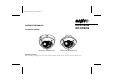
L5AK4/US, L5AL4/US GB 2003, 6, 6 INSTRUCTION MANUAL COLOR CCD CAMERA VDC-D1184VA (SURFACE TYPE) VDC-D1184VA VDC-D2184VA VDC-D2184VA (IN-CEILING TYPE) About this manual Before installing and using the camera, please read this manual carefully. Be sure to keep it handy for later reference.
L5AK4/US, L5AL4/US GB 2003, 6, 6 Depending on the conditions of use, installation and environment, please be sure to make the appropriate settings and adjustments. If you need help with installation and/or settings, please consult your dealer. CONTENTS INFORMATION TO USER....................................................................... 2 PRECAUTIONS........................................................................................ 3 INSTALLATION..................................................
L5AK4/US, L5AL4/US GB 2003, 6, 6 INFORMATION TO USER Safety Guard THIS SYMBOL INDICATES THAT THERE ARE IMPORTANT OPERATING AND MAINTENANCE INSTRUCTIONS IN THE LITERATURE ACCOMPANYING THIS UNIT. WARNING: TO PREVENT THE RISK OF FIRE OR ELECTRIC SHOCK , DO NOT EXPOSE THIS APPLIANCE TO RAIN OR MOISTURE. For the customers in Canada This Class B digital apparatus complies with Canadian ICES-003. Pour la clientèle canadienne Cet appareil numerique de la Classe B est conforme a la norme NMB-003 du Canada.
L5AK4/US, L5AL4/US GB 2003, 6, 6 PRECAUTIONS In case of malfunction Do not use the camera if smoke or a strange odour comes from the unit, or if it seems not to function correctly. Disconnect the power supply immediately, and consult your dealer (or a Sanyo Authorized Service Center). Do not open or modify Do not open the cabinet, as it may be dangerous and cause damage to the unit. For internal settings and repairs, consult your dealer (or a Sanyo Authorized Service Center).
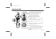
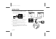
L5AK4/US, L5AL4/US GB 2003, 6, 6 INSTALLATION Note: When setting up this camera, make sure that it is installed securely. If it (Model VDC-D1184VA) is not installed correctly, it may fall down. In addition, do not touch the camera in places except where settings and adjustments are necessary. (Model VDC-D2184VA) Coaxial cable type and maximum length 73mm (G) (H) (H) (G) (D) (D) • Cable type RG-59U (3C-2V), 250 m maximum. • Cable type RG-6U (5C-2V), 500 m maximum.
L5AK4/US, L5AL4/US GB 2003, 6, 6 INSTALLATION 6 Pass the power cable/day-night cable (G) and video cable (H) from the camera unit through the cable hole in the ceiling. Connections AC 24 V connection DC 12 V connection (Power cable/day-night cable) DC12 AC24 Cable RED BLACK WHITE GND YELLOW COLOR PURPLE B/W + ~ – ~ Power cable Align the four screw holes in the camera unit (C) with the screw holes in the ceiling, and then secure the camera in place by tightening the screws.
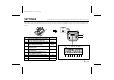
L5AK4/US, L5AL4/US GB 2003, 6, 6 SETTINGS The illustration shows the factory default settings for the switches in the camera setup section. When changing the settings and adjustments for this camera, loosen the camera unit screw (A) and remove the lens unit in the direction of the arrow. When changing the DIP switch settings, take care when making the settings and adjustments because power is still being supplied to the camera.
L5AK4/US, L5AL4/US GB 2003, 6, 6 SETTINGS C • B/W (color/black and white) switch setting This switch lets you select the timing of the automatic switching of the optical filter to color image or black and white image, according to the subject brightness. The default setting is down (LOW). Set the switch according to the brightness. High speed electronic shutter setting Normally, the speed setting switches for the high speed electronic shutter are all set to the down (OFF) position.
L5AK4/US, L5AL4/US GB 2003, 6, 6 SETTINGS Backlight compensation setting This camera has two different backlight compensation functions: Normally backlight compensation switch 5 (BL-M) and 6 (BL-C) are set to the down (OFF) position. Change the backlight compensation switch settings 5 6 depending on the conditions. • BL-M mode: Use this position when applying backlight (Multi-spot) compensation to the whole of the screen.
L5AK4/US, L5AL4/US GB 2003, 6, 6 SETTINGS White balance adjustment Normally the switch 7 (WB) is set to the down (ATW: auto white balance) position and the white balance is adjusted automatically. If a manual white balance adjustment is necessary, follow the steps below. Set the switch 7 (WB) to the up (MANU: manual) position, then adjust the color. • Turn R (VR302) to set the red ratio and/or B (VR303) to set the blue ratio.
L5AK4/US, L5AL4/US GB 2003, 6, 6 SETTINGS Manual color/black and white setting Lens iris adjustment Connect each cable as indicated below, to set the image to black and white or color as desired. • Color image setting Connect the Color (yellow) and the White (ground) cables. • Black and white setting Connect the B/W (purple) and the White (ground) cables.
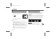
L5AK4/US, L5AL4/US GB 2003, 6, 6 ADJUSTMENT Once the camera has been installed, adjust the lens section. Adjusting the lens 1 Model: VDC-D2184VA 1 Model: VDC-D2184VA Loosen the pan adjustment screw, adjust the panning position of the lens and then re-tighten the screw.
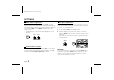
L5AK4/US, L5AL4/US GB 2003, 6, 6 ADJUSTMENT TROUBLESHOOTING MONITOR output pin When setting up the camera, connect a monitor to this video output pin and to the GND screw using alligator clip cables, then using the image displayed on the monitor, set the surveillance angle and range, the lens focus, etc. Before taking the camera for repairs, please check below to make sure that the camera is used correctly.
L5AK4/US, L5AL4/US GB 2003, 6, 6 SPECIFICATIONS Interlace : PLL 2:1 interlace Environmental conditions : Temperature: –10° C ~ +50° C Humidity: less than 90% (no condensation) Image device : 1/4 inch solid state image device CCD Power supply : 24 V AC, 60 Hz and 12 – 15 V DC Picture elements : 811 (H) x 508 (V) Power consumption : 2.9 W Weight : VDC-D1184VA: Approx. 1,350 g VDC-D2184VA: Approx.
L5AK4/US, L5AL4/US GB 2003, 6, 6 SANYO INDUSTRIAL VIDEO COLOR VIDEO CAMERA LIMITED WARRANTY OBLIGATIONS In order to obtain warranty service, the product must be delivered to and picked up from an Authorized Sanyo Service Center at the user’s expense, unless specifically stated otherwise in this warranty. The names and addresses of Authorized Sanyo Service Centers may be obtained by calling the toll-free number listed below.
L5AK4/US, L5AL4/US GB 2003, 6, 6 Printed on recycled paper SANYO Electric Co., Ltd.