
Quick Installation Guide
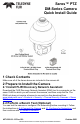

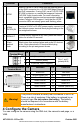
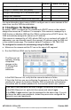
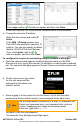
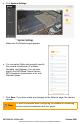
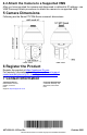
Table Of Contents

427-0200-01-10 Rev 120
October 2021
This document does not contain any export-controlled information.
Connector
Connection
1
UPOE
Attach a Cat 5e or Cat 6 cable from the network switch
to the RJ45 connector for a 10/100/1000 Mbps Ethernet
and PoE connection. If using PoE, use a FLIR CP-POE-
4P-60W-xx injector or a switch that supports Universal
PoE 60W 4 pair forced mode. For more information
about compatible injectors and recommended switches,
contact Teledyne FLIR support. Verify that the UPOE
connector LEDs are steady green and flashing yellow.
2
AC24V
(DC30V) IN
If using a 24 VAC or 30 VDC power supply, connect it to
the three-pin power terminal block plug according to the
pin assignment shown.
3
DEFAULT
To reset factory defaults at any time, press the Default
button for at least 20 seconds.
4
14-pin
terminal
block
Attach wires from external alarm and audio I/O devices
to the 14-pin alarm/audio I/O terminal block plug
according to the pin assignment shown.
3-Pin Power
Terminal Block
Pin
24 VAC
30 VDC
1
L (Live; white; positive)
Pins 1 and 3
(polarity N/A)
2
Ground (Earth)
3
N (Neutral; black; negative)
14-Pin Alarm/Audio I/O
Terminal Block
Pin
Definition
Pin
Definition
1
Audio-Out
8
Not used
2
Ground (Audio I/O)
9
Alarm-In 4
3
Alarm-Out A1
10
Alarm-In 3
4
Alarm-Out A2
11
Alarm-In 2
5
Alarm-Out B1
12
Alarm-In 1
6
Alarm-Out B2
13
Ground (Alarm I/O)
7
Not used
14
Audio-In
Warning!
This product contains a battery that is soldered to the PCB.
There is a risk of explosion if the battery is replaced by an
incorrect type. Do not replace the battery. The battery
should be disposed of in accordance with the battery
manufacturer’s instructions.
4 Configure the Camera
You can configure the camera using the DNA tool, the camera's web page, or a
VMS.