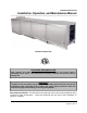
Pollution Control Unit Installation, Operation, and Maintenance Manual Pollution Control Unit RECEIVING AND INSPECTION Upon receiving unit, check for any interior and exterior damage, and if found, report it immediately to the carrier. Also check that all accessory items are accounted for and are damage free. WARNING!! Installation of this unit should only be performed by a qualified professional who has read and understands these instructions and is familiar with proper safety precautions.
TABLE OF CONTENTS WARRANTY .................................................................................................................................................. 4 LISTINGS ...................................................................................................................................................... 5 APPLICATION .............................................................................................................................................. 5 INSTALLATION ....
WARRANTY This equipment is warranted to be free from defects in materials and workmanship, under normal use and service, for a period of 12 months from date of shipment. This warranty shall not apply if: 1. The equipment is not installed by a qualified installer per the MANUFACTURER’S installation instructions shipped with the product, 2. The equipment is not installed in accordance with federal, state and local codes and regulations, 3. The equipment is misused or neglected, 4.
LISTINGS This pollution control unit (PCU) is ETL listed to standard UL-710, CAN/ULC-S646, CAN/ULC-S647 when installed in accordance with these installation instructions and National Fire Protection Association Standard “NFPA 96, Standard for Ventilation Control and Fire Protection of Commercial Cooking Operations.” APPLICATION The listed pollution control unit is suitable for use in commercial cooking installations for the removal of smoke and grease laden vapors.
INSTALLATION It is imperative that this unit is installed and operated with the designed airflow, filters, exhaust fan placement, and construction in accordance with this manual. If there are any questions about any items, please call the service department at 1-866-784-6900 for warranty and technical support issues. WARNING: DO NOT RAISE PCU BY THE DOOR, FILTER FRAMES, OR UTILITY CABINET – USE LIFTING LUGS PROVIDED OR A SLING. Site Preparation 1.
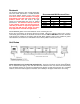
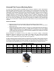
Ductwork The ductwork attached to this unit will significantly affect the airflow performance. Flexible ductwork and square elbows should not be used. There must be at least 3 duct diameters of straight duct leading to the inlet and at the outlet of the pollution control unit. The chart to the right shows the recommended duct sizes for optimal performance.
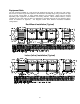
Equipment Rails The unit should be installed on a curb and/or rail elevated not less than 14” above any roof surface. Secure PCU to rails through vertical portion of the PCU base assembly flange using a minimum of eight (8) lug screws, anchor bolts, or other suitable fasteners (not furnished). Shims may be required depending upon equipment rail installation and roofing material. When installed indoors, uni-strut channels may be used under the PCU for attachment to threaded rod from the roof structure above.
Air Pressure Switch Option Switches are preset from plant to .15” w.c. above the internal static pressure of the PCU with clean filters. Air pressure switch is located in downstream filter module. Route wiring from hood control panel to PCU using ½” conduit through quick seal located near lower right area of filter module containing switch. Use existing conduit in module to route wires from exterior of module to switch. Install wiring according to label above switch. Be sure all conduit fittings are tight.
Advanced Filter Pressure Monitoring Option The PCU Filter Monitoring Module (PCUFMM) utilizes proprietary algorithms to make determinations about filter loading percentages as well as fault conditions, such as missing filters and missing doors.
The HMI for the PCU filter pressure monitor is a “Smart” rocker switch installed with a built in organic LED monochrome graphic display. The rocker switch has three momentary switches, one is actuated when the top portion of the rocker is depressed, the second one is actuated when the middle portion of the rocker is depressed and the third is actuated when the bottom portion of the rocker is depressed. General Navigation Rules • Top button is used to go to the previous menu.
• Config PCU is configured at the factory. PCU has to be re-configured ONLY if filter types in any filter module are changed. To Configure the PCU a 4 digit PIN (5678) is entered using middle and bottom buttons. The following are the sub menus available Configure PCU modules • This sub menu steps through the process of configuration. Module count for the PCU assembly is entered followed by the filter type for each module. • The bottom button is used to step though the available filter types.
PCUFMM Wiring Before connecting power to the control, read and understand the entire section of this document. As-built wiring diagrams are furnished with each control by the factory, and are attached either to the door of the unit or provided with the paperwork packet. Electrical wiring and connections should be done in accordance with local ordinances and the National Electric Code, ANSI/NFPA 70.
Troubleshooting The following table lists causes and corrective actions for possible faults shown on the HMI with the Pollution Control Units. Review this list prior to consulting manufacturer.
Fire System Pollution Control Units often require a fire system to be installed with the PCU. CORE or Ansul R-102 Fire Suppression Systems are available for the PCU. PCU fire systems use fusible links or electric sensors set at 360°F to activate the fire system. Outdoor Ansul R-102 installations require a climate controlled cabinet to ensure the fire system does not drop below 32°F and does not exceed 130°F. See below for more information about outdoor installations.
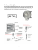
Utility Cabinet Pollution Control Unit with Climate Controlled Utility Cabinet Installed 16
OPERATION Prior to starting up or operating the PCU, check all fasteners for tightness. In particular, check the module connection seal and the door seals. With power to the fan OFF, check the airflow direction of the filters as they must match the label on the filter. Start Up Special Tools Required • • 3M Fire Barrier 2000 + Silicone Sealant Standard Hand Tools Start Up Procedure 1. 2. 3. 4. 5. 6. Check all fasteners and connections for tightness.
Troubleshooting The following table lists causes and corrective actions for possible problems with the pollution control units and the fan attached to the PCU. Review this list prior to consulting manufacturer.
MAINTENANCE To guarantee trouble free operation of this PCU, the manufacturer suggests following these guidelines. Most problems associated with PCU failures are directly related to poor service and maintenance such as not replacing or cleaning filters. Please record any maintenance or service performed on this fan in the documentation section located at the end of this manual. WARNING: DO NOT ATTEMPT MAINTENANCE ON THE PCU UNTIL THE ELECTRICAL SUPPLY HAS BEEN COMPLETELY DISCONNECTED FROM THE FAN.
WARNING: FILTER PART NUMBERS OUTLINED BELOW ARE LISTED FOR USE IN THE PCU.
450° F Gasket between Modules and doors 1500° F Gasket for Internal Joints Gasket Type Chart Gasket Type High Temp Closed Cell (Orange) High Temp Ceramic (White) Application Exterior Seam Between Modules Internal Seams Size 3/16” x 1” ¼” x 1” Temp Rating Part Number 450°F 1500°F SNS200A-1/4x1 397-91PSA 2 Weeks After Startup 1. Inspect the unit and duct for grease or air leaks and repair leaks where required. 2.
Start-Up and Maintenance Documentation START-UP AND MEASUREMENTS SHOULD BE PERFORMED AFTER THE SYSTEM HAS BEEN AIR BALANCED (Warranty will be void without completion of this form) Job Information Job Number Address City State Zip Phone Number Fax Number Contact Purchase Date Service Company Address City State Zip Phone Number Fax Number Contact Start-Up Date PCU Information Refer to the start-up procedure in this manual to complete this section.