
Product Manual


For parts or assistance, call Flotec Customer Service at 1-800-365-6832
General Information 3
GENERAL INFORMATION
Tanks listed below are pre-charged, or filled with
air at the factory, to 40 pounds per square inch
(PSI) (276kPa). When installing tank, set tank pres-
sure according to Chart 1. To do this, bleed air from
or add air to tank through valve on top of tank.
NOTICE: Always set or check tank pre-charge with
NO WATER in tank or water pressure in system. If
you have already pumped water before setting or
checking pre-charge pressure, turn pump off. Open
faucet until there is no more water pressure. Set
pre-charge in tank according to Chart 1, then close
faucet and turn pump back on.
NOTICE: Replace and tighten air valve cap after
pressure is adjusted correctly. Failure to replace air
cap may allow loss of air pressure and lead to tank
waterlogging and bladder failure.
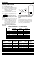
CHART I
(The first number on the pressure switch is the
pump on setting; the second number is the pump
off setting.)
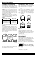
Pre-charged storage tanks can be connected togeth-
er to increase the drawdown. Drawdown is the
actual amount of usable water available from when
the tank is full to when the pump turns on.
Installing two tanks of same size will double the
drawdown supply, three tanks will triple the draw-
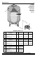
down supply, (Figure 1). Locate pressure switch as
shown. Tank and pressure switch cannot be more
than 10’ (3M) apart.
NOTICE: Tank capacity is different than drawdown.
Tank capacity is the actual physical volume of the
sheet metal that makes up the tank.
OPERATING CYCLE (FIGURE 2)
Step 1. Tank nearly empty – air expands filling area
above bladder (Figure A).
Step 2. Water enters tank – air is compressed
above bladder as it fills with water (Figure
B).
Step 3. Pump-up cycle completed – air compressed
to OFF setting of pressure switch (Figure C).
Step 4. Water drawn from tank – compressed tank
air forces water out of bladder (Figure D).
Step 5. Bladder empty – new cycle ready to begin
(Figure A).
Connect discharge pipe from pump to a tee.
Connect one side of tee to tank flange and the
other side of tee to service. Use plastic or steel pipe
as required. To prevent leaks, use Teflon tape or
Plasto-Joint Stik
1
on male threads of all threaded
connections to tank.
STANDARD TANK
REPLACEMENT
When replacing standard tank in a water system
with pre-charged tank, no bleeder orifices or Air
Volume Control (AVC) are required. When sizing a
pre-charged tank to replace a standard tank, the
tanks should have equivilant drawdowns. For
example, model FP7110T precharged tank has a
drawdown of 5.8 gallons (22L) and is equivalent to
a 42 gallon standard tank that has a drawdown of
4.3 gallons (16.3L).
Hazardous voltage and hazardous
pressure. Disconnect all power to pump and bleed
all pressure from system before working on pump,
tank, or piping.
1
Lake Chemical Co., Chicago, Illinois
When Pressure Switch Reduce Tank
Setting Is Precharge (PSI) To
20-40 PSI (138-276 kPa) 18 (124 kPa)
30-50 PSI (207-345 kPa) 28 (193 kPa)
40-60 PSI (276-414 kPa) 38 (262 kPa)
To serviceFrom well
909 0993
Tanks
Pressure
switch
Figure 1
Figure 2
WATER
AB
WATER
WATER
CD