
Product Manual


Installation 4
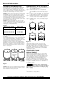
For jet pump installation, remove AVC tube from
port in pump body or jet body and plug port (see
Figure 3). New pumps come with plug installed.
NOTICE: When working on submersible pumps in
wells be sure safety rope is solidly connected to
pump and to secure anchor at the well head at all
times. Do not drop the pump down the well!
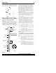
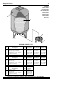
NOTICE: For submersible pump installations, there
may be bleeder orifices in the vertical discharge
pipe. When the bleeder orifices are functioning
correctly, they add air to the water in the system.
They must be removed and the tees plugged when
a pre-charged tank is installed in the system. To do
this, raise the pump and discharge piping enough
to bring the bleeder orifices clear of the well.
Remove the bleeder orifices from tees and replace
with plugs (see Figure 4). Bleeder orifices may be
any of several sizes. Have a pair each of 1/2”, 3/4”,
and 1” plugs available. Replace pump and recon-
nect the discharge pipe.
NOTICE: To be sure joint is not cross-threaded and
threads are clean, make connections by hand (with-
out sealer) first. When threads are clean, remove
pipe, add Teflon tape or Plasto-Joint Stik, and
remake connection. Tighten by hand first; finish
with pipe wrench.
In areas where temperature is high for long periods
of time, tank pre-charge pressure may increase.
This may reduce tank drawdown (amount of water
available per cycle). If this occurs, adjust pre-
charge pressure according to Chart 1, page 3.
Flush all air out of piping system and water reser-
voir portion of pre-charged tank. Required on: new
installations, pumps requiring repriming, and
pumps disassembled for service. Do as follows:
Step 1. Open faucets furthest from tank and run
pump.
Step 2. Run pump until sputtering stops and steady
stream of water flows.
Step 3. Open and close faucets repeatedly until all
air has been removed.
Step 4. If stream does not become steady, air may
be leaking into system; check for leaks in
piping on suction side of pump.
NOTICE: To prevent waterlogging, check tank air
charge annually.
TO CHECK TANK AIR CHARGE
If drawdown decreases significantly, check as fol-
lows:
Step 1. To check air charge in tank, shut off electric
power to pump, open faucet near tank, and
drain completely.
Step 2. At air valve, check tank air pressure with
tire gauge. See Chart 1, page 3, for correct
pressure setting. If needed, adjust tank pres-
sure up or down.
Step 3. Use soap or liquid detergent to check for
air leaks around air valve. Continuous bub-
bling indicates leak. If necessary, release air
pressure and install new core in air valve,
(same as used for automobile tubeless tires.)
For parts or assistance, call Flotec Customer Service at 1-800-365-6832
148 0893
Figure 3: Plug AVC Port when installing
pre-charged tank on existing pumps. New
pumps come with plug Installed.
Pitless
adaptor
Check valve
Bleeder orifice
& tee
Pipe coupling
Tape cable
to pipe
Pump
Ventilated
well cap
Submersible
cable
2 ft.
(.6m)
158 0893
Figure 4