
Application Note


3 Fluke Corporation Using a Fluke ScopeMeter 125 to Troubleshoot FOUNDATION™ Fieldbus Installations
where humidity or poor air have
corroded connectors. Or, perhaps
vibration has caused intermittent
connections.
In verifying new installations, it
makes sense to test trunk cabling
before installing spurs and
devices. Eliminating the trunk
cabling as a source of a problem
in an existing network or as the
potential source of problems in
a new network requires a few
simple measurements. The digital
multimeter incorporated into the
Fluke 125 measures the resis-
tance and capacitance of cables.
If problems exist, using these
capabilities will detect them.
1. The first step in verifying
trunk cabling is to measure the
capacitance between individual
conductors and the shield. The
two values (conductor A versus
the shield and conductor B versus
shield) should yield about the
same value because the trunk is
supposed to be fully symmetrical.
In making these measurements,
compare the capacitance val-
ues to the data for the type of
cable used, and take the length
of the trunk into account. (An
example of a manufacturer’s cable
specifications can be found in the
appendix to this application note.)
When a Fluke 125 is the test
instrument, the test involves
connecting the TL75 lead to the
shield connector in control room
and applying the hot tip of the
STL120 to the A and the B wires
respectively. Depending upon the
length of the trunk, it may take
a few seconds for a capacitance
reading to stabilize. When a
reading is stable, record it.
2. Next, measure the capacitance
between the two conductors, A
and B, by connecting the TL75 to
one wire and the ‘hot’ tip of the
STL120 to the other wire contact.
Record the result.
Failure to get a reading for any
of the three capacitances proba-
bly indicates a short or a broken
connection in that section of the
circuitry. An unstable reading
may signal a weak connection
in a junction box that is creating
only intermittent contact with a
section of the trunk.
If the capacitances conform
to expectations, create a short
circuit at the end of the trunk
between the A and B wires and
measure the resistance between
those conductors on the control
room side. This measurement
should produce a reading rep-
resenting the total resistance of
the copper conductors over the
total length of the trunk, back
and forth. A comparison of this
reading with the specifications
for the cable will reveal whether
there are any poor connections
anywhere along the trunk. Bear
in mind that while cable speci-
fications may give the resistance
per conductor for a single length
of wire, this test measures the
return path, too.
3. Next, remove the short cir-
cuit at the end of the trunk
and measure the resistance
between the A wire and shield,
and between the B wire and
shield. The readings should be
high, in the multiple meg-ohms
range. A low value indicates
a short circuit to the shield.
A short might be caused by
something as seemingly insig-
nificant as a single thin wire
from a braid that’s making
contact near a screw terminal,
or it might be an indication of
a cable defect or the result of
moisture in a junction box.
4. Once you are confidence that
all resistance and capacitance
values for the trunk meet expec-
tations and match the cable
specifications, inspect the spurs.
On new installations, this will
follow the initial connection and
testing of each spur. Once each
spur checks out, repeat the pre-
vious tests to find and correct
errors in the whole system. If
everything checks out, it’s safe
to power up the network.
Supply voltage
Each of the network devices
needs the proper supply voltage.
Incorrect dc-supply can cause
a variety of errors—sometimes
continuously and sometimes
intermittently. Incorrect supply
voltage can cause devices to
fail to handle data consistently,
frequently disconnecting and
reconnecting or perhaps not
responding to the controller at all.
Since supply voltage is distrib-
uted through the main network,
which may be lengthy, there
will be voltage drop within
the system. The absolute mini-
mal dc-supply voltage for any
Fieldbus device is 9 volts, but a
higher voltage is preferable. The
absolute maximum supply volt-
age is 32 volts.
The Fluke 125 ScopeMeter test
tool can measure supply voltage
and automatically compare it to
an upper and a lower limit. As
defaults, these limits are set for
5.5 and 35.0 volts. However, the
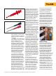
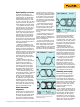
Figure 3: HC120 Hook Clip
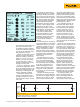
Figure 4: TP88 Back Probe-pins