
Application Note

2 Fluke Corporation Basic power quality measurements on the go with the Fluke 345
Waveform view
The world runs on ac voltage, be it at home, shop-
ping center, hospital, factory, or industrial complex.
Sometimes valuable troubleshooting information
can be gained by “viewing” the ac waveforms
behind the action. Turn the Fluke 345 switch to
and you can view the voltage and current wave-
forms. From there, select either of the waveforms
and use the arrow keys to measure voltage at a
specific point on the waveform, as well as the time
between two points on the waveform.
Armed with the waveform and harmonics data,
you have a good chance of understanding why the
electrical system, and the equipment connected to
it, are behaving the way they are. For example, if
the voltage waveform is flattened on top, you may
find some equipment will reset or operate errati-
cally, because its electronic power supplies aren’t
functioning properly. If the current is drawn in
short pulses instead of a sine wave, it’s likely that
you have an electronic load and potential harmon-
ics problems.
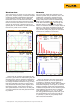
Figure 1. The dual waveform display on the Fluke 345
shows both voltage and current waveforms.
Harmonics
One of the most talked about problems in the
electrical systems today is harmonics, due to the
proliferation of computers, variable frequency
motor drives, and electronic lighting. A power
quality clamp meter is ideal for troubleshooting
these types of problems. Set the switch of the
Fluke 345 to harmonics ( )to see voltage and
distortion factor (% THD rms). Once the clamp
meter is in harmonics mode, it’s a simple matter to
switch to a view of the fundamental voltage and
THD, and to evaluate the individual harmonics,
up to the 40
th
, using a bar graph. All of the same
information is available for current also.
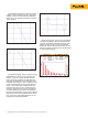
Figure 2. Graph harmonics for voltage and current.
What are harmonics and what causes them?
The electrical system that we use generates an
ac voltage at a frequency of 60 Hz (Hertz) or
50 Hz in some parts of the world. This is called the
fundamental frequency of the system, or the first
harmonic. Distortion results from the introduction
of additional frequencies into the electrical system.
These additional frequencies occur at multiples
of the line frequency, i.e. 2, 3, 4, 5, etc, times
the utility generated frequency. Most often, you’ll
see odd harmonics, such as the third (180 Hz),
5
th
(300 Hz), 7
th
(420 Hz), and possibly others
above the seventh harmonic.