
Application Note


3 Fluke Corporation Measuring uncommon RTDs with the Fluke 726
Setting up communications
The Fluke 700SC Serial Interface Cable (PN
667425) is used to communicate with the Fluke
726. The serial cable connects to the round multi-
pin connector at the top of the 726 and to a 9-pin
serial port on your PC. The serial cable can only
interface with one instrument or module at a time.
After connecting the cable, make sure the 726
is turned on. Call up the Windows HyperTerminal
Program. It is usually listed in the Windows Start
Programs menu under Accessories, Communica-
tions. The HyperTerminal program will ask you
to set up a file name to store your communication
settings. You can select any icon and click OK to
continue.
A second dialog box, “Connect To”, will pop up.
Skip down to the bottom, where it says “Connect
Using:” Select the COM port you connected to
the 726.
Loading custom RTD constants into the Fluke 726
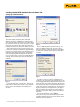
Next, a COM Properties box will come up. Set
baud rate (9600 in Figure 4), data bits, parity,
stop bits and flow control as shown in the Figure
4. Once your settings match Figure 4, click OK to
continue.
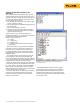
To make it easier to read the commands and
responses, you can make some adjustments to the
way the HyperTerminal program treats screen text.
Under the File menu select Properties and click on
the Settings tab. Click on the button labeled ASCII
Setup. You will see a dialog like the one shown in
Figure 5. Match the settings shown in the figure.
Note that adding the 200 ms line delay makes it
possible to send short scripts to the 726. More on
this later.
To test the connection, type:
*idn?
After you hit Enter, the 726 should respond with
“FLUKE,726,0,X.X” where X.X is the version of the
firmware in the instrument.
Figure 2.
Figure 3.
Figure 4.
Figure 5.