Victoreen® Digital Preamplifier, Model 943-227-15,for use with Model 943-27 Current Mode Beta Detector Operator Manual February 2008 Manual No. 943-227-15-1, Rev. 3 ©2007, 2008 Fluke Corporation, All rights reserved. Printed in U.S.A.
Fluke Biomedical 6045 Cochran Road Cleveland, Ohio 44139 440.498.2564 www.flukebiomedical.
Table of Contents Section 1: 1.1 1.2 1.3 1.4 1.5 1.6 1.7 General Information ............................................................................................................. 1-1 General Description ............................................................................................................... 1-1 Application.............................................................................................................................. 1-1 Specifications ...........................
(Blank page)
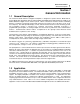
General Information General Description 1 Section 1 General Information 1.1 General Description The Victoreen® Model 943-227-15 Digital Preamplifier, is designed to operate with the Model 943-27, Current Mode Beta Scintillation detector and the Model 942A-200C Series Digital Ratemeter (UDR) or the Model 960 Series Digital Process Control system.
943-227-15 Digital Preamplifier Operator Manual Table 1-1.
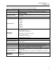
General Information Application 1 Table 1-2. General Specifications for the 943-227-15 Digital Preamplifier Feature: Specification: + 15 v @ 20 mA Preamplifier Power DC current, 1E-12 to 1E-3 amperes from 943-27 Current Mode Beta Preamplifier Input Scintillation detector 943-227-15, RS232C; 943-227-15VL, Modified RS232C serial data for transmission distances up Preamplifier Output to 5,280 feet.
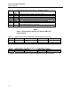
943-227-15 Digital Preamplifier Operator Manual Table 1-3. Preamplifier Serial Interface Board 977-210-10M Switch Settings Switch Normal Switch Function Op.
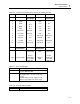
General Information Specifications 1 Table 1-6.
943-227-15 Digital Preamplifier Operator Manual 1.4 Auxiliary Equipment Model Description None 1.5 Recommended Spare Parts Table 1-9. Recommended Spare Parts List for the Model 943-227-15 Digital Preamplifier Part Number Description Used On 977-200-15M Electrometer Circuit Board 977-210-10M Serial Interface Circuit Board 92-7072 Fuse, F1, F2, 1Amp, Communication Fuse 977-210-10M 450-1-0531 Dryer, Air (5 Grams) 977-200-15 1.6 Receiving Inspection Upon receipt of the unit: 1.
General Information Spare Parts/Receiving Inspection 1 1.7 Storage Storage of Fluke Biomedical instruments must comply with Level B storage requirements as outlined in ANSI N45.2.2 (1972) Section 6.1.2(.2). The storage area shall comply with ANSI N45.2.2 (1972) Section 6.2 Storage Area, Paragraphs 6.2.1 through 6.2.5. Housekeeping shall conform to ANSI N45.2.3 (1972).
(Blank Page)
Theory of Operation Functional Description 2 Section 2 Theory of Operation 2.1 Functional Description The Model 943-227-15 Digital Preamplifier is an eight-decade, linear reading radiation. The preamplifier is sensitive to moisture and is mounted in a NEMA 4 sealed enclosure. The preamplifier box contains a desiccant package to remove moisture from the interior of the preamplifier. The desiccant has a color indicator to show when it should be replaced when the color changes to blue.
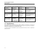
943-227-15 Digital Preamplifier Operator Manual 0/-12 Vdc INTEGRATING ELECTROMETER 0 - 10 Vdc ALARM OUTPUT PGA DAC EPROM ANALOG SWITCH MICROPROCESSOR ADC SIGNAL CONTROL HIGH VOLTAGE POWER SUPPLY HIGH VOLTAGE ACIA Resistor +VL DETECTOR ASSEMBLY RS232 Resistor VICO LOOP +TX -TX +RX MICROPROCESSOR CONTROL SIGNAL Figure 2-1. Typical Detector Electronics Block Diagram Table 2-1.
Theory of Operation Main Circuit Boards 2 Table 2-2.
943-227-15 Digital Preamplifier Operator Manual The following Test are provided on the 977-200-15M board: Table 2-4. 977-200-15M Test Points Test Point Function TP1 Electrometer Output TP2 Analog +5 VDC supply TP3 - 5 VDC supply TP4 Digital +5 VDC supply (From 977-210-10M) TP5 High Voltage Sense (Not Used) TP6 + 12 VDC supply (From 977-210-10M) TP7 DC Ground TP8 Programmable Gain Amplifier Output TP9 Microprocessor Clock Signal TP10 Chip Enable - EPROM 2.
Theory of Operation Communications 2 Victoreen Communications Loop – 943-227-15VL Communication between the detector preamplifier and the UDR or 960 controller may be performed via Victoreen loop, a serial asynchronous communications interface. The communication utilizes Victoreen protocol and is intended for use in electrically hostile environments where high noise immunity is required.
943-227-15 Digital Preamplifier Operator Manual Table 2-8. Jumper Positions for Preamplifier Serial Interface Board 977-210-10M Jumper Normal Function Alternate Function Setting Setting JMP1 A to B B to C Enables RS232C Enables Victoreen Loop (normal) JMP2 N/A Deleted, Not Used N/A Deleted, Not Used Table 2-9. Jumper Positions for Preamplifier Electrometer Board 977-200-15M Jumper Normal Function Cal.
Operation Installation 3 Section 3 Operation 3.1 Installation Installation consists of mounting the equipment, making the required electrical connections, and entering the desired set points. CAUTION Remove all power prior to installing the Preamplifier. Preamplifier Mounting The preamplifier is a self-contained unit that is designed for mounting on a wall, or structurally sound surface, within 6 feet of the detector.
943-227-15 Digital Preamplifier Operator Manual NOTE The electrometer circuitry in the preamplifier is highly sensitive to moisture and physical damage. Use extreme care when the preamplifier case is opened as the high impedance electrometer circuitry is easily damaged. Do not leave the preamplifier enclosure in the open position for any extended period of time. The preamplifier terminations are listed below. Table 3-1.
943-227-15 Digital Preamplifier Operator Manual 3-3
Operation Configuration 3 3.3 Operation Operation of the 943-227-15 Digital Preamplifier is automatic and is controlled by the Model 942A-200C Digital Ratemeter or Model 960 Digital Process Radiation monitoring system. Once the power to the controlling device is turned on, the preamplifier begins operation. No operator interaction is required. Refer to the instruction manual for the applicable controller, detector and the Model 942-200-80 Communications Option Board for further information.
943-227-15 Digital Preamplifier Operator Manual For UDR systems, the address of the 942-200-80 Communications board in the UDR must be set 4040 and the baud rate must be set to 4800 baud. If the wiring of the Communications option board to the P2 connector is suspected, a loop test can be performed as described in "Loop Test Mode". The instruction manual for the Communications option board (P/N 942-200-80-1) contains information on how to set up the serial board in the UDR.
Operation Configuration 3 3.5 Set Point Error Codes Failure of the 943-227-17 preamplifier may result in the following error codes being displayed on the controlling device: Code E0009 is normally used to identify a Loop communication failure. The error code may be due to a baud rate mismatch between the preamplifier and the UDR or 960 system communication board, a failure on either the preamplifier or UDR communication board. To clear the error code, the source of the error must be corrected. 3.
(Blank page)
Maintenance, Calibration and Troubleshooting Maintenance 4 Section 4 Maintenance, Calibration and Troubleshooting 4.1 Maintenance The 943-227-15 Digital Preamplifier is designed to operate for extended periods of time with no scheduled maintenance required. Operation may be verified by periodically actuating the check source (provided with the detector and sampling assembly) and observing the response of the unit.
943-227-15 Digital Preamplifier Operator Manual 4.3 Troubleshooting WARNING Extreme care must be used when troubleshooting a system that has power applied. All standard troubleshooting precautions apply. WARNING Once a problem has been located, remove all power before continuing with the repair. CAUTION Personnel performing the troubleshooting/repair must be qualified to ANSI 45.2.6, 1978, Skill Level II.
Appendix Connector Designations A Appendix A Connector Designations A.1 CONNECTOR DESIGNATIONS, 943-227-15 and 943-227-15VL Table A-1.
943-227-15 Digital Preamplifier Operator Manual A.2 SWITCH AND JUMPER POSITIONS, 943-227-15 and 943-227-15VL Table A-2. Preamplifier Serial Interface Board 977-210-10M Switch Settings Switch Normal Switch Function Op.
Appendix Applicable Drawings B Appendix B Applicable Drawings B.1 Applicable Drawings 943-227-15 and 943-227-15VL Drawing No.
(Blank page)
Appendix Bill of Materials C Appendix C Bill of Materials C.
(Blank page)
Appendix Cable Termination Instructions D Appendix D Cable Termination Instructions D.1 Cable Termination Instructions The procedures and instructions provided in Appendix D are provided for reference in terminating the field cables to the Digital Preamplifier. A mating SHV connector is provided with the preamplifier. Ring lug terminals are to be provided by the user. The instructions provided below are based on the use of P/N 50-100 multi-conductor cable.
943-227-15 Digital Preamplifier Operator Manual Detector Field Cable Preparation, 943-227-15VL-M1, Conduit Hub: Prior to terminating the cable, the field conduit must be run to the junction box, and the field cable pulled into the junction box. To prepare the cable for termination, a minimum of 7 inches of the cable outer jacket must be stripped off the cable. This will allow for the stripping of approximately one inch from the various conductors, and provide 6 inches of actual service loop cable.
Appendix Cable Termination Instructions D HV CONNECTOR NOTES (HV) The mating HV connector, P/N 30-92-1 (Kings 1705-14), may now be terminated per the applicable Kings data sheet attached LOCATION P/N DOCUMENT DESCRIPTION SHV SHV 92-9105-A (1705-1) CP-400, Kings Cabling Procedure, Trim Code 441, 442 High Voltage Connector, SHV, male crimp contact pin (Use Tool KTH-100 with KTH-2062) SHV Alternate Connector 92-9105-A (51426-5) AMP Instruction Sheet 408-2187 High Voltage Connector, SHV, male crim
943-227-15 Digital Preamplifier Operator Manual D-4
Appendix Cable Termination Instructions D D-5
943-227-15 Digital Preamplifier Operator Manual D-6
Appendix Cable Termination Instructions D D-7
943-227-15 Digital Preamplifier Operator Manual D-8
Appendix Modifications E Appendix E Modification Sheets, Engineering Instructions E.1 Modification Sheets, Engineering Instructions P/N Description 943-227-15VL-M1 Modification consists of replacing the standard 8in H x 10in W x 4in D Enclosure with a 8in H x 10in W x 6in D Enclosure and replacing the field cable “Seal Grip” type entry fitting with a 2.0 in diameter sealed conduit fitting.
(Blank page)
(Blank page)
Fluke Biomedical 6045 Cochran Road Cleveland, Ohio 44139 440.498.2564 www.flukebiomedical.