
Stereo Amplifier User Manual


General Information
Specifications
1
1-
5
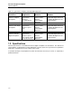
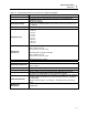
Table 1-6. Field Electrical Connections, 943-227-15 and 943-227-15VL
943-227-15
943-27-15VL
TB1- Description
Connects To
977-210-10M
Description
Connects To
977-210-10M
1 XMIT
J4-1
+ VL, 15
VDC
J3-1
2 DTR
J4-2
+ TX
J3-2
3 GND
J4-3
- TX
J3-3
4 REC
J4-4
- VL
J3-4
5
Not Used
Not Used
+ RX
J3-5
6
Not Used
Not Used
- RX
J3-6
7 + 15 VDC J3-7 Not Used
Not Used
8 Ground
J3-8
Ground
J3-8
9 - 15 VDC J3-4 Not Used Not Used
10 Not Used Not Used Not Used J3-11
Detector
Connections
Detector
Connections
HV Detector MHV
From Field
coaxial cable
Detector
MHV
From Field
coaxial cable
SIG Detector BNC
Factory
Terminated,
To 977-200-
15M, R41
Detector
BNC
Factory
Terminated,
To 977-200-
15M, R41
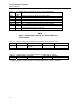
Table 1-7. 977-210-10M LEDs
LED # Indicates
LED1 +15 VDC is being supplied to the circuit board
from the UDR when ON
LED2 Communications – Receive;
ON (bright): both + 15 and -15 volt loops
present
ON (dim): Only one loop supply present
OFF: no loop voltage from either supply
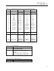
Table 1-8. 977-210-10M Test points
Test Point Function
TP2 RS232 Transmit