® 2680A/2686A Data Acquisition System/Data Logging System Getting Started Guide June 2002 © 2002 Fluke Corporation. All rights reserved. Printed in USA All product names are trademarks of their respective companies.
Limited Warranty and Limitation of Liability Each Fluke product is warranted to be free from defects in material and workmanship under normal use and service. The warranty period is one year and begins on the date of shipment. Parts, product repairs and services are warranted for 90 days.
Safety Information WCaution This is an IEC safety Class 1 product. Before using, the ground wire in the line cord or rear panel binding post must be connect to an earth ground for safety. Interference Information This equipment generates and uses radio frequency energy and if not installed and used in strict accordance with the manufacturer’s instructions, may cause interference to radio and television reception.
SAFETY TERMS IN THIS MANUAL This device has been designed and tested to meet the requirements of EN61010-1 (Safety Requirements for Electrical Equipment for Measurement, Control and Laboratory Use). It is an Installation Category II device intended for operation from a normal single phase supply. The DIO relay controls are rated to 250 V ac CAT I and should not be used in applications that exceed that rating. This Getting Started Guide contains information, warnings and cautions.
XWWARNING Use the proper fuse. To avoid fire hazard, for fuse replacement use only a 1/2 ampere, 250 V time delay line fuse. DC POWER SOURCE The device may also be operated from a 9 V to 45 V dc power source when either the rear panel ground binding post or the power cord grounding conductor is connected properly. The input is protected by a 4 ampere fuse internal to the device. This fuse should only be replaced by a qualified Fluke technician.
XWWARNING DO NOT OPERATE IN EXPLOSIVE ATMOSPHERES To avoid personal injury or death, do not remove the device cover without first removing the power source connected to the rear panel. Do not operate the device without the cover properly installed. There is no need for the operator to remove the cover. DO NOT ATTEMPT TO OPERATE IF PROTECTION MAY BE IMPAIRED If the device appears damaged or operates abnormally, protection may be impaired. Do not attempt to operate the device under these conditions.
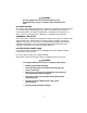
Additional Safety Information The following table provides additional safety information. General Specifications Specification Characteristic Size 473 mm (18.6 in) x 423 mm (17 in) x 237 mm (9.3 in) Weight 2680A/2686A (empty) 8.5 Kg (18.9 lb) 2680A – FAI 2680A – PAI 2680A – DIO 0.8 Kg (1.8 lb) 1.2 Kg (2.7 lb) 0.8 Kg (1.
vi
Table of Contents Contents Page Safety Information........................................................................................... i Introduction ..................................................................................................... 1 Contacting Fluke ............................................................................................. 2 Additional Information.................................................................................... 2 Configuring the 268XA.......
2680A/2686A Getting Started Guide Module Configuration Dialog .............................................................. Analog Channel Configuration Dialog ................................................ DIO Configuration Dialog ................................................................... Computed Channel Configuration Dialog............................................ Communication Dialogs...........................................................................
Getting Started Introduction The 2680A Data Acquisition System (DAS) and 2686A Data Logging System (DLS) provide 20 to 120 channels that operate in conjunction with Fluke DAQ software to form a data acquisition system. The 2686A comes with a removable PC Card (PCMCIA) for stand-alone storage operation. This socket accepts ATA memory cards up to 2 GB in size. Each 268XA device can hold from 1 to 6 analog modules.
2680A/2686A Getting Started Guide Contacting Fluke To contact Fluke, call one of the following telephone numbers: USA: 1-888-99-FLUKE (1-888-993-5853) Canada: 1-800-36-FLUKE (1-800-363-5853) Europe: +31 402-675-200 Japan: +81-3-3434-0181 Singapore: +65-738-5655 Anywhere in the world: +1-425-446-5500 Or, visit Fluke’s Web site at www.fluke.com.
Getting Started Configuring the 268XA Configuring the 268XA You must configure the 268XA device before using it. The following sections provide basic configuration information. Refer to the Users Manual for additional configuration information. Reviewing and Setting the Base Channel Number Perform the procedure below to review or set the Base Channel Number (BCN). The BCN identifies the device.
2680A/2686A Getting Started Guide REVIEW Communications display for reviewing the Base Channel Number (BCN) SET Communications display for setting the BCN SET Base Channel Number display for setting the BCN 10s digits (for example, 45) REVIEW Base Channel Number display for reviewing the BCN number (for example, 45) CH Front Panel display for an device with BCN 45 Figure 1.
Getting Started Configuring the 268XA Reviewing and Setting the Line Frequency Perform the procedure below to review or set the line frequency. Line frequency selection allows the device to optimize internal circuitry for best accuracy. (See Figure 2 for examples.) • Line Frequency Choices Select 50 Hz or 60 Hz as the frequency of the primary power when an ac source powers the device. Table 2.
2680A/2686A Getting Started Guide REVIEW Communications display for reviewing the line frequency SET Communications display for setting the line frequency SET Hz Line frequency display for setting the line frequency to 60 Hz SET Hz Line frequency display for setting the line frequency to 50 Hz REVIEW Hz Line frequency display for reviewing the line frequency (60 Hz) Figure 2.
Getting Started Configuring the 268XA Reviewing and Setting the Network Type Perform the procedure in below to review or set the network type to isolated. Perform the procedure in Table 4 to review or set the network type to general. An isolated network consists of only 268XA Series and NetDAQ 26X devices and one or more host computers. A general network consists of devices, host computers, and possibly servers, routers, gateways, or other network devices. (See Figure 3 for examples.
2680A/2686A Getting Started Guide REVIEW Communications display for reviewing the network type SET Communications display for setting the network type SET Network display for setting the network type to isolated SET Network display for setting the network type to general REVIEW Network display for reviewing the network type (isolated network) Figure 3.
Getting Started Configuring the 268XA If you set Fluke DAQ Software for general network operation, you must set the network type of each device to general. You will need to enter an IP address, and possibly a socket port, subnet mask and gateway address into each device. Get this information from your network administrator. Table 4. Reviewing and Setting the Network Type to General Press the COMM key to review the network type, or press and hold the COMM key for 3 seconds to set the network type.
2680A/2686A Getting Started Guide REVIEW Communications display for reviewing the network type SET Communications display for setting the network type SET Network display for setting the network type to general SET Socket Port display for setting the first digit (for the example 04369) SET Socket Port display for setting the second digit (for the example 04369) Figure 4.
Getting Started Configuring the 268XA SET IP address display for setting an IP:0 digit (for example, 129:196:152:101) SET IP address display for setting an IP:1 digit (for example, 129:196:152:101) SET IP address display for setting an IP:1 digit (for example, 129:196:152:101) SET IP address display for setting an IP:2 digit (for example, 129:196:152:101) SET IP address display for setting an IP:3 digit (for example, 129:196:152:101) Figure 4 Examples for Reviewing and Setting General Network Param
2680A/2686A Getting Started Guide Reviewing and Setting the General Network Socket Port Perform the procedure below to review or set the general network Socket Port (1024 to 65535). The default is 04369. In order to communicate with each other, a host computer and an device must use the same socket port number. (See Figure 4 for examples.) • General Network Socket Port Enter the Socket Port supplied by your network administrator. Table 5.
Getting Started Configuring the 268XA Reviewing and Setting the General Network IP Address Perform the procedure below to review or set the device’s general network Internet Protocol (IP) address. • General Network IP Address Enter the IP Address supplied by your network administrator for each BCN. The format is four 3 digit segments: IP0.IP1.IP2.IP3. Table 6.
2680A/2686A Getting Started Guide Reviewing and Setting the Subnet Mask and Default Gateway If communication between the host computer and the 2680 Series passes through a router or gateway, you must set the subnet mask and default gateway address on both the host computer and the device. Get this information from your network administrator. Perform the procedure in Table 7 to review or set the device network gateway parameters.
Getting Started Configuring the 268XA The network number of the device must match that of the gateway. For example, if the gateway IP address is 129.196.180.93, and the subnet mask is 255.255.255.0, the network number is 129.196.180.0, and the device IP address must be in the range 129.196.180.1 to 129.196.180.254. Table 7. Reviewing and Setting the Subnet Mask and Default Gateway Press the COMM key to review the parameters, or press and hold the COMM key for 3 seconds to set the parameters.
80A/2686A Getting Started Guide Viewing the Device Ethernet Address Perform the procedure in below to view the Device Ethernet address. (See Figure 5 for examples.) The network administrator must know the device Ethernet address when the device operates on a general network. You do not need this information when you operate the device on an isolated network. • Ethernet Address Format The Ethernet address is a 12 digit hexadecimal number. For example, 00:80:40:12:34:56.
Getting Started Configuring the 268XA REVIEW Communications display for viewing the device Ethernet address REVIEW Ethernet address display for viewing byte 0 (for example 00-80-40-12-34-56) REVIEW Ethernet address display for viewing byte 2 (for example 00-80-40-12-34-56) REVIEW Ethernet address display for viewing byte 4 (for the example 00-80-40-12-34-56) REVIEW Ethernet address display for viewing byte 5 (for example 00-80-40-12-34-56) Figure 5.
2680A/2686A Getting Started Guide Host Computer and Network Preparation This section contains information for preparing your host computer and setting up network communication, as summarized below. Installing Host Computer Ethernet Adapter Skip this section if you have an Ethernet adapter installed on your computer. Since the installation procedures for Ethernet adapters change frequently and without notice, you must follow the instructions supplied with your particular Ethernet adapter.
Getting Started Host Computer and Network Preparation 1 Install Ethernet Adapter Ethernet Card OR PC Card 2 Interconnect Host Computers and Instruments Instrument 3 Install Networking Software Windows 98/NT or higher 4 Install Fluke DAQ Software Fluke DAQ for Windows alg02f.eps Figure 6.
2680A/2686A Getting Started Guide Device and Host Computer Interconnection You may interconnect 268X devices and host computer(s) with 10/100 BaseT (twisted pair) wiring. If your site is already wired, you can use the wire in place. If your site is not wired, you are connecting your device directly to your host computer.
Getting Started Host Computer and Network Preparation Direct connection between a single host computer and a single device with 10/100BaseT is possible, but you must use a special cable that has its transmit and receive lines crossed. The typical general network configuration uses 10BaseT Twisted Pair Ethernet for interconnection (shown).
2680A/2686A Getting Started Guide Installing Host Computer Networking Software To establish Ethernet communication in your host computer, you must do the following: • Install a driver for the adapter • Install TCP/IP protocol stack • Set host computer networking parameters This section discusses installing the adapter driver and the TCP/IP protocol stack. You should install the networking software that is most appropriate for your operating system. Windows 98, Windows NT (Service Pack 6.
Getting Started Host Computer and Network Preparation Setting Host Computer Networking Parameters This section discusses how to set your host computer networking parameters after you install your adapter and networking software. If you plan to use Fluke DAQ software for general network operation, and you are just now enabling networking, you must set the host computer’s IP address, subnet mask, and possibly its default gateway IP address. Obtain this information from your network administrator.
2680A/2686A Getting Started Guide Introducing Fluke DAQ Software Fluke DAQ software provides a graphical user interface (GUI) to the 264XA and 268XA family of data acquisition products. You can use Fluke DAQ software to easily perform the following: Note Fluke DAQ supports the NetDAQ devices (2640A and 2645A) as well as the 2680A and 2686A. • Configure your 268XA network and device settings. • Download/upload configuration to the devices.
Getting Started Installing Fluke DAQ Software Note You will need to reboot your computer after you install the Fluke DAQ software. During installation, the following directories and files are installed on you PC. alg100s.bmp The Fluke DAQ subdirectories contain the following information Alarm Collected alarm data and format information. Config Miscellaneous files used in a system configuration. Database Miscellaneous files that related to the database collection.
2680A/2686A Getting Started Guide Understanding the User Interface Fluke DAQ software has a standardized and easy to use interface. This section explains the components of the interface. Using the Toolbar A toolbar appears on all of the Fluke DAQ dialogs. Use the toolbar buttons to add and configure devices 268XA devices and to navigate through the Fluke DAQ application. Each button on the toolbar has a tool tip that identifies the button function. Using the mouse, point to a button to view the tool tip.
Getting Started Understanding the User Interface Table 3-1. Fluke DAQ Toolbar Buttons (cont) Button Function Trend button. Used to access the Trend dialog to view the scanned data collected from 268XA devices. Alarm button. You can use the Alarm View dialog to view On Line and History alarms. The Alarm status icon can also assume two states in the TreeView panel. When an alarm is activated the Alarm icon turns red.
2680A/2686A Getting Started Guide Understanding the Workspace Area The Workspace Area consists of a network TreeView and a set of buttons. Use the Workspace Area to: • Open, Save, and Remove configuration files. You can also use the Save As button to rename an existing configuration file.
Getting Started Understanding the User Interface Checking Operational Status The icons in the TreeView change to indicate the device status. Below are all the possible icons and their meaning: Device Status Icon • Yellow or blue device icons indicates the device is not connected. • Green device icon indicates the device is connected and communicating. • Red device icon indicates an device error.
2680A/2686A Getting Started Guide Configuration Dialogs The Configuration dialog that appears depends on the node (device, module, or channel) you select in the TreeView panel. You can also use copy and paste functionality to save configuration time. Channel settings can be copied from one channel to another in the same device, or you can copy a whole module or a group of channel settings from one device to another.
Getting Started Understanding the User Interface Note The Save command saves the actual 2686A configuration to the PC Card. The Load command loads the configuration from the PC Card to the 2686A. • Set up the device general settings • Specify which module will control the trigger out signal for master/slave operation Module Configuration Dialog A 268XA device can have up to 6 modules with specific configuration settings. The Module Configuration dialog appears when you select a module in the TreeView.
2680A/2686A Getting Started Guide Communication Dialogs The Communication dialogs display the communication status of connected network components and allow you to interact with those components. Fluke DAQ uses the following Communication dialogs.
Getting Started Understanding the User Interface Trend Dialog You can use the Trend dialog to view the scanned data collected from the 268XA devices. The charts can be On Line or Historical. You can use the Export button to export data to a CSV file that you can manipulate using Excel. Alarm Dialog You can use the Alarm View dialog to view On Line and History alarms. You can filter the alarms by device ID, module and channel.
2680A/2686A Getting Started Guide Managing Your Network Using Fluke DAQ The following procedures provide detailed instructions for using Fluke DAQ to: • Insert and configure 268XA devices, modules, channels, and computed channels. • Start a scan • View scan data. • View alarms. Inserting and Configuring a 268XA Device To insert and configure a device 1. Double-click the icon on your desktop to start Fluke DAQ. 2. Specify basic settings in the Fluke DAQ Application dialog. alg102s.
Getting Started Managing Your Network Using Fluke DAQ The dialog box entries include: Configuration file button or the Click the configuration file. button the to load an existing Network Type Isolated if the PC is connected directly to the 268XA device or General if the 268XA is part of a network. Port Number 4369 is the default port number. Fluke recommends that you use the default port number. Group is externally wired All devices may be wired together in a master/slave arrangement.
2680A/2686A Getting Started Guide 4. Specify the Base Channel (1 to 99) and Device Type and click OK. A device is attached to the new configuration. As part of the insertion process, you can specify a base channel number. This number is used to differentiate channels in different devices. You can insert up to 99 Base Channels of the same Device Type. The Base Channel number auto-increments when you add devices. alg104s.bmp Note Fluke DAQ also supports 2640A and 2645A NetDAQ devices.
Getting Started Managing Your Network Using Fluke DAQ 6. Set the IP Address on the Device Settings dialog. Other fields are optional. You may need to contact your Internet support staff to determine the IP Address. alg106s.bmp The dialog box entries include: IP Address Enter the IP Address of the device you are adding. Verify Button Click the Verify button to ping the device and verify that the IP Address is correct. The device and your PC must both be connected to the network for this to work.
2680A/2686A Getting Started Guide Monitor Channel Select a channel measurement to display on the device front panel. You can also choose to increment though active channels or to automatically scan through all active channels. Default is None. Scan Parameters Parameters you can set to start, stop, and save scan data. Note You can also select Start Scan on Power Up for stand-alone operation or to automatically start scanning after a power loss.
Getting Started Managing Your Network Using Fluke DAQ Inserting and Configuring a Module To insert and configure a module 1. Highlight a device in the TreeView panel and click the Insert button. alg107s.bmp 2. Specify the number and type of modules you want to insert in the Module dialog box. alg108s.bmp The dialog box entries include: Module Number You can attach up to 6 modules to the device. You can only have a Digital I/O in Module Slot 6 and can have only one per device.
2680A/2686A Getting Started Guide 3. Click OK. The modules are added to the device and appear in the TreeView panel. alg109s.bmp 4. Select one of the analog modules you inserted and the Analog Module settings dialog appears. alg110s.
Getting Started Managing Your Network Using Fluke DAQ The dialog box entries include: Interval Trigger Uses the interval timer (interval 1 timer) to set the scan rate for normal operation in a module. The interval is user settable. External Trigger Uses the Trigger input signal to start a scan. Every time the external trigger is activated, another scan is taken. Alarm Trigger Uses a second interval timer (interval 2 timer) to start scanning when an alarm condition is encountered by the module.
2680A/2686A Getting Started Guide Note If you are configuring a DIO module, the Totalizer Configuration dialog appears. alg111s.bmp The dialog box entries include: Start Count Used to specify a start count. Debounce Select debounce to ignore signals with a period less than 2 ms (500 Hz); otherwise, signals up to 5 kHz can be counted. Direction If you entered a start count, the start count is reloaded when the totalizer reaches the terminal count. The totalizer can count up or down to zero.
Getting Started Managing Your Network Using Fluke DAQ Inserting and Configuring a Channel After selecting a module, you need to add channels to the module. To insert and configure a Channel 1. Highlight a module in the TreeView panel and click the Insert button. alg112s.bmp 2. Specify the number of channels you want to insert on the Insert Channel dialog box. alg113s.bmp 3. Click OK. The channels are added to the module and appear in the TreeView panel. alg114s.
2680A/2686A Getting Started Guide 4. Select a channel and the Module settings dialog appears. alg115s.bmp The dialog box entries include: CH # XX-YYY. The first two digits identify the chassis (01-99). The next digit identifies the module (1-6), and the last two digits identify the channel (1-20). Label Use the label field to identify where the channel is used in your application. Unit Label Used to identify the unit of measurement (°C or °F). Function Identifies the type of measurement being performed.
Getting Started Managing Your Network Using Fluke DAQ Alarm 1 or Alarm 2 Each channel has two alarms. You can set the alarms to Off, Low, or High. An alarm condition occurs when a measurement falls below a low alarm value (Low) or rises above a high alarm value (High). Fluke DAQ records all alarm conditions in a data file. Open Thermocouple Detection Provides for notification if an open thermocouple is detected. Factors (Mx+B) Used to scale measurements.
2680A/2686A Getting Started Guide 2. Specify the number of channels you want to insert on the Insert Channel dialog box. alg117s.bmp 3. Click OK. The computed channels are added and appear in the TreeView panel. alg118s.
Getting Started Managing Your Network Using Fluke DAQ 4. Select a computed channel and the Computed Channel settings dialog appears. alg119s.bmp The dialog box entries include: CH # Computed channels are assigned channel numbers from 901 to 960. Label Use the label field to identify where the computed channel is used. Unit Label The value to apply to the label. For example, you may want the calculated value shown as Watts.
2680A/2686A Getting Started Guide Alarm 1 or Alarm 2 Each channel has two alarms. You can set the alarms to Off, Low, or High. An alarm condition occurs when a measurement falls below a low alarm value (Low) or rises above a high alarm value (High). Fluke DAQ records all alarm conditions in a data file. Digital Output Used to output a digital signal or close a relay if an alarm is detected. Use Channel as Alarm Trigger Select if channel reading will be used to trigger an alarm.
Getting Started Managing Your Network Using Fluke DAQ Using Equations with Computed Channels Each computed channel can have an expression of 250 characters but the maximum number of characters available in all 60 channels is limited to 6,000 characters. For example, you could use an equation to calculate the rate of flow in gallons per second. The rate of flow could be calculated as follows. Since TS is in milliseconds, you need to divide by 1000 to calculate gallons per second.
2680A/2686A Getting Started Guide alg120s.bmp The following is a list of the valid notations. Axxx Alarm on/off (Boolean value of 1 or 0) Cxxx Any channel measurement C9xx Computed channel TS Time since last measurement (milli seconds) TOT Totalizer Operators +, -, *, /, **, unary +, unary -, abs, exp, int, ln, log, and sqr.
Getting Started Managing Your Network Using Fluke DAQ Starting a Scan You can scan for data using a configuration scan, a device scan, or by using Spy. All scanning options are available in the Communication window. Note You must have channels configured for operation before starting a scan. Starting a Configuration Scan To start a configuration scan on the Fluke DAQ toolbar and highlight the configuration in 1. Click the the TreeView panel. 2. Click to start the scan. Click to stop the scan. alg121s.
2680A/2686A Getting Started Guide Starting a Device Scan To start a device scan on the Fluke DAQ toolbar and highlight a device in the 1. Click the TreeView panel. 2. Click to start the scan. Click to stop the scan. alg122s.
Getting Started Managing Your Network Using Fluke DAQ Starting a Scan Using Spy Spy triggers and collects its own measurements from up to eight channels from any combination of devices. The data is not stored and the devices you are checking do not need to be scanning. To start a Spy scan on the Fluke DAQ toolbar. The Spy icon appears in the lowest 1. Click the item in the TreeView panel. 2. Click the Spy icon and the Spy window appears. You may select up to 8 channels, including DIO and totalizer.
2680A/2686A Getting Started Guide Viewing Module Measurement Data You can view measurement data from a module as it is recorded. Selecting a module shows all 20 channels as for the Computer Channels. Modules that have no channels configured display question marks. NC indicates that a channel is not configured. To view module measurement data 1. Click the on the Fluke DAQ toolbar. 2. Highlight a module in the TreeView panel and the module measurement data appears. alg124s.
Getting Started Managing Your Network Using Fluke DAQ Using the Digital I/O Points Communication Dialog You can use the Digital I/O Points Communication dialog to set any of the 8 relays or 20 DIO pins active when an alarm condition occurs in the channel. You can also view status of all of the relays and DIO pins and set or clear IO bits and relays. Bits or relays you set display a green dot. Bits or relays set by an alarm have a red dot. A bit set by an external signal has a blue dot.
2680A/2686A Getting Started Guide Using Trend to View Collected Data You can use the Trend dialog to view the scanned data collected from the 268XA devices. The charts can be On Line or Historical. You can use the Export button to export data to a CSV file that you can manipulate using Excel. You can select up to eight channels to view on the strip chart. If a particular channel is not active, question marks are displayed. A horizontal cursor is used to find the time a signal reached a certain amplitude.
Getting Started Managing Your Network Using Fluke DAQ The dialog box entries include: Pen Click to select the device, module, or channel that you want to view in the chart. You can view up to 8 items on the chart. Type Specify On Line or History scan view. History view shows the last set of data displayed with the pens. Zoom Use Use to expand or compress the time interval you are viewing.
2680A/2686A Getting Started Guide alg127.bmp Device ID Any device from 1 to 99. Module A specific module in a device or you can select all of the modules. Start Date/Start Time Start Date and Start Time are used to select the data. Data is stored with the date the scan began. Duration Duration is the amount of time to be converted. Note that the maximum time allowed for the conversion to a .csv file is 24 hours CSF file The directory where the converted file will be stored.
Getting Started Managing Your Network Using Fluke DAQ Changing the Chart Display To change the strip chart display • The Trend Setting dialog appears when you double-click on the chart screen. Use the Trend Settings dialog to change the location of the upper and lower boundary points, the scaling seen on the chart, and the color of the plot pens you are using. alg128s.
2680A/2686A Getting Started Guide Viewing Alarms You can use the Alarm View dialog to view On Line and History alarms. You can filter the alarms by device ID, module and channel. When an alarm occurs, the color of the device icon in the configuration window changes to red. As long as the alarm exists, the icon remains red. In the Alarm window, a red line of information shows the status of the alarm. If the alarm condition goes away before you acknowledge the alarm, the alarm icon changes to blue.
Getting Started Managing Your Network Using Fluke DAQ The dialog box entries for On Line include: Type Specify On Line or History alarm view. Ack Click the appropriate button to acknowledge the Last Alarm or All Alarms. Alarm Device Filters Choose to view alarms from a select set of devices, modules, and channel. When you choose the History option, you can view alarms over a period of time. Each time an alarm changes state the new color is added to the history screen.
2680A/2686A Getting Started Guide Alarm Device Filters Choose to view alarms from a select set of devices, modules, and channel. Using Fluke DAQ System Security Features You can use the system security features to protect device configuration information. The system security feature allows the administrator to add and remove Fluke DAQ users, allow other users to configure devices, and to change user passwords. Only the administrator (Root user) can use the security system configuration function.
Getting Started Managing Your Network Using Fluke DAQ Configuring Web and Alarm Mail Settings You can use the Web and Alarm Mail Settings dialog to enter Fluke DAQ web configuration information and to configure Fluke DAQ to send e-mail messages reporting alarm condition. The Web Settings portion of dialog is used to specify a URL where scanned values from your 268XA device will be sent.
2680A/2686A Getting Started Guide The dialog box entries include: Data Server IP Address The IP address of the computer running the Fluke DAQ application. Fluke DAQ fills in this field with the first IP address found on the computer. Note You must change this setting if you want to use a different interface or if you are using a Dynamic Host Configuration Protocol (DHCP) on your server. If you are using a DHCP server, use the computer name instead of an IP address.