Timer/Counter/ Analyzers PM6680B, PM6681, PM6681R, PM6685 & PM6685R Programming Manual
All rights reserved. Reproduction in whole or in part is prohibited without written consent of the copyright owner. TimeView is a trademark of Pendulum Instruments AB. FLUKE is a trademark of Fluke Corporation. TimeView uses the SPAWNO routines by Ralf Brown to minimize memory use while shelling to DOS and running other programs.
Table of Contents 1 Getting Started ‘C’ for National Instruments PC-IIA . . . . . . . . . . . . . . . . . . . . . . . . . . . . 4-13 Finding Your Way Through This Manual . . 1-2 Manual Conventions . . . . . . . . . . . . . . . . . 1-3 Setting Up the Instrument . . . . . . . . . . . . . 1-4 Interface Functions . . . . . . . . . . . . . . . . . . 1-5 1. Limit Testing . . . . . . . . . . . . . . . . . . . . 4-14 2. REAL Data Format . . . . . . . . . . . . . . . 4-15 3. Frequency Profiling . . . . . . . . .
General Speed Improvements. . . . . . . . . . 7-8 40000 measure- ments/second . . . . . . . . 7-11 Supervising a Process. . . . . . . . . . . . . . . 7-12 Speed Summary . . . . . . . . . . . . . . . . . . . 7-17 Diagnostics Subsystem . . . . . . . . 9-29 :DIAGnostic:CALibration:INPut[1|2]:HYSTeresi s . . . . . . . . . . . . . . . . . . . . . . . . . . . . . . 9-30 Display Subsystem . . . . . . . . . . . . 9-31 :DISPlay :ENABle . . . . . . . . . . . . . . . . . . 9-32 8 Error Messages Fetch Function. . .
:MEASure :FREQuency :RATio?. . . . . . . 9-63 :MEASure [:VOLT] :MAXimum? . . . . . . . 9-64 :MEASure [:VOLT] :MINimum? . . . . . . . . 9-64 :MEASure :NWIDth? . . . . . . . . . . . . . . . . 9-65 :MEASure :PWIDth? . . . . . . . . . . . . . . . . 9-65 :MEASure_«:PDUTycycle/ :DCYCle»? . . 9-66 :MEASure_«:NDUTycycle»? . . . . . . . . . . 9-66 :MEASure :PERiod? . . . . . . . . . . . . . . . . 9-67 :MEASure :PHASe? . . . . . . . . . . . . . . . . 9-67 :MEASure [:VOLT] :PTPeak? . . . . . . . . .
∗OPC? . . . . . . . . . . . . . . . . . . . . . . . . . . 9-125 ∗OPT? . . . . . . . . . . . . . . . . . . . . . . . . . . 9-125 ∗PSC . . . . . . . . . . . . . . . . . . . . . . . . . . . 9-126 ∗PMC. . . . . . . . . . . . . . . . . . . . . . . . . . . 9-126 ∗PUD . . . . . . . . . . . . . . . . . . . . . . . . . . . 9-127 ∗RCL . . . . . . . . . . . . . . . . . . . . . . . . . . . 9-127 ∗RMC. . . . . . . . . . . . . . . . . . . . . . . . . . . 9-128 ∗RST . . . . . . . . . . . . . . . . . . . . . . . . . . .
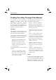
Chapter 1 Getting Started
Getting Started Finding Your Way Through This Manual You should use this Programming The ‘Programmers Reference’ SecManual together with the tion of this manual contains: PM6680B/1/5 Operators Manual. That manual contains specifications – Chapter 5, Instrument Model explains how the instrument looks for the counter and explanations of from the bus. This instrument is the possibilities and limitations of the not quite the same as the one used different measuring functions. from the front panel.
Getting Started Manual Conventions Syntax Specification Form This manual uses the EBNF (Extended Backus-Naur Form) notation for describing syntax. This notation uses the following types of symbols: n Printable Characters: Printable characters such as Command headers, etc., are printed just as they are, e.g. period means that you should type the word PERIOD.
Getting Started used if the command is only four characters. – If the last character in the command is a digit, then this digit is appended to the shortform. Examples: Longform Shortform :MEASURE :MEAS :NEGATIVE :NEG :DREGISTER0 :DREG0 :EXTERNAL4 :EXT4 The shortform is always printed in CAPITALS in this manual: :MEASure, :NEGative, :DREGister0, :EXTernal4 etc.
Getting Started The address can also be set via a GPIB command or from the AUX MENU on the PM6680B/1/5. The set address is stored in nonvolatile memory and remains until you change it. Power-on When turned on, the counter starts with the setting it had when turned off.
Getting Started n Listener Function, L4 The counter can receive programming instructions from the controller. L4 means that it has the following functions: – Basic listener. – No listen only. – Automatic un-addressing as listener when addressed as a talker. n Service Request, SR1 The counter can call for attention from the controller, e.g., when a measurement is completed and a result is available.
Chapter 2 Bus Commands for the Benchtop User
Bus Commands for the Benchtop User :INP:FILT8ON|OFF :INP:IMP850|1E6 :INP:SLOP8POS|NEG Switches on or off the 100kHz LP-filter Sets the input impedance 50Ω or 1MΩ Positive or negative trigger slope :INP:ATT81|10 :INP:COUP8AC|DC :INP:LEV8 Attenuation 1X or 10X Level can be set to between –5.1 to + 5.
Bus Commands for the Benchtop User :DISPL:ENAB8ON|OFF :ROSC:SOUR8INT|EXT* :SYST:PRES or *RST Presets the counter to default P M 6 6 8 1 R R E F A D J L O C A L P R E S E T U N L O C K / S T A N D B Y E X T R E F F IL T E R O N 1 X / 1 0 X F R E Q U E N C Y R E F E R E N C E /C O U N T E R /C A L IB R A T O R IN P U T A 5 0 / 1 M A C / D C / A S W A P / B T R IG G E R L E V E L S E T A A U T O S E T B IN P U T B 5 0 / 1 M A C / D C C O M A 1 X / 1 0 X C H E C K T O T S T /S T
Bus Commands for the Benchtop User :FUNC8"functionc8hannel,channel" * :ACQ:APER8
Bus Commands for the Benchtop User :CALC:MATH8 () Expression is mathematical expression containing +, –, *, /, and XOLD XOLD in a mathematical expression gives the same result ar pressing Xn-1 :CALC:MATH:STAT8ON|OFF Not used via bus; enter constants directly in the mathematical expression :CALC:AVER:TYPE8MAX|MIN|SDEV|MEAN Selects statistical function :CALC:AVER:STAT8ON|OFF R U B ID IU M 5 0 p s /3 0 0 M H z F U N C T IO N M E N U A U X M E N U M E A S U R E M E N T T R IG A P R O C
Bus Commands for the Benchtop User :FUNC8"FREQ:RAT81,2" :FUNC8"FREQ:RAT83,2" :FUNC8"PER81" :FUNC8"PWID81" :FUNC8"FREQ83" :FUNC8"TINT81,2" :FUNC8"FREQ81" :FUNC8"PHAS81,2" REMOTE :FUNC8"RISE|FALL:TIME81" This segment is on when the instrument is controlled from GPIB. Press LOCAL to interrupt bus control.
Bus Commands for the Benchtop User PM6680B IN P U T A 9 0 V -2 6 5 V IN P U T B P A N E L IN P U T S A N A L O G O U T P U T 1 6 8 4 2 1 A D D R E S S P M 9 6 7 8 P M 9 6 9 0 P M 9 6 9 1 P M 9 6 2 1 P M 9 6 2 4 P M 9 6 2 5 P M 9 6 2 6 P M P M _ _ _ _ G A T E O P E N R E A R IN P U T C O N O F F 9 9 _ _ _ _ 6 2 6 9 _ _ _ _ IE E E 4 8 8 /IE C 6 2 5 IN T E R F A C E S H 1 , A H 1 , T 5 , L 4 , S R 1 , R L 1 , D C 1 , D T 1 , E 2 8 /8 0 7 _ _ 1 0 M H z O U T R E F E R E N C E IN E X T A R M
Bus Commands for the Benchtop User Default settings (after *RST) PARAMETER VALUE/ SETTING PARAMETER VALUE/ SETTING Mathematics OFF Sample size in Statistics 100 Sample size in Time Interval Average 100 Input A: Mathematical constants: Trigger level AUTO Impedance K= and M= 1 1 MΩ L= 0 Manual Trigger level 0V (Controlled by autotrigger) Manual Attenuator 1X (Controlled by autotrigger) Coupling AC Trigger slope Pos Filter OFF Input B: Miscellaneous: Function FREQ A Timeout
Chapter 3 Introduction to SCPI
Introduction to SCPI What is SCPI? SCPI (Standard Commands for Programmable Instruments) is a standardized set of commands used to remotely control programmable test and measurement instruments. The CNT-8X firmware contains the SCPI. It defines the syntax and semantics that the controller must use to communicate with the instrument. Compatibility SCPI provides two types of compatibility: Vertical and horizontal.
Introduction to SCPI Management and Maintenance of Programs SCPI simplifies maintenance and management of the programs. Today changes and additions in a good working program are hardly possible because of the great diversity in program messages and instruments. Programs are difficult to understand for anyone other than the original programmer. After some time even the programmer may be unable to understand them.
Introduction to SCPI How does SCPI Work in the Instrument? The functions inside an instrument that control the operation provide SCPI compatibility. Figure 3-3 shows a simplified logical model of the message flow inside a SCPI instrument. When the controller sends a message to a SCPI instrument, roughly the following happens: – The GPIB controller addresses the instrument as listener. – The GPIB interface function places the message in the Input Buffer.
Introduction to SCPI State IDLE READ Purpose Wait for messages Read and execute messages QUERY Store responses to be sent SEND Send responses REComplete sending reSPONSE sponses DONE Finished sending responses DEADLOCK The device cannot buffer more data Action, Unterminated, Reason The controller attempts to read the device without first having sent a complete query message Interrupted, The device is interrupted by a new program message before it finishes sending a response message message.
Introduction to SCPI Remote Local Protocol The Counter in Remote Operation n Definitions When the Counter is in remote operation, it disables all its local controls except the LOCAL key. Remote Operation When an instrument operates in remote, all local controls, except the local key, are disabled. Local Operation An instrument operates in local when it is not in remote mode as defined above. Local Lockout In addition to the remote state, an instrument can be set to remote with ‘local lockout’.
Introduction to SCPI Program and Response Messages The communication between the system controller and the SCPI instruments connected to the GPIB takes place through Program and Response Messages. A Program Message is a sequence of one or more commands sent from the controller to an instrument. Conversely, a Response Message is the data from the instrument to the controller. C o n tr o lle r ; < P ro g ra m Fig 3-6 M e s s a g e U n it> Syntax of a terminated Program Message.
Introduction to SCPI Most controller programming languages send these terminators automatically, but allow changing it. So make sure that the terminator is as above. Example of a terminated program message: :INP:IMP 1E6;:ACQ:APER 0.1NL^END program message unit terminator program message unit This program message consists of two message units. The unit separator (semicolon) separates message units.
Introduction to SCPI Notation Habit in Command Syntax To clarify the difference between short and longform, the shortform in a syntax specification is shown in upper case letters and the remaining part of the longform in lower case letters. Notice however, that this does not specify the use of upper and lower case characters in the message that you actually sent.
Introduction to SCPI Command Tree Command Trees like the one below are used to document the SCPI command set in this manual. The keyword (mnemonic) on the root level of the command tree is the name of the subsystem. The following example illustrates the Command Tree of the INPut1 subsystem. < H E A D E R > :IN P u t[1 ] :IM P e d a n c e P a ra m e te rs & < N u m e r ic v a lu e > |M A X |M IN [:S T A T e ] + SEND→ INPut:EVENt:HYSTeresis Where: INPut is the root node and HYSTeresis is the leaf node.
Introduction to SCPI This is the command where: INPut:EVENt is the header path and :HYSTeresis is the first leaf-node and LEVel is the second leaf node because LEVel is also a leaf-node under the header path INPut:EVENt. There is no colon before LEVel! + Parameters Numeric Data Decimal data are printed as numerical values throughout this manual. Numeric values may contain both a decimal point and an exponent (base 10). These numerals are often represented as NRf (NR = NumeRic, f = flexible) format.
Introduction to SCPI n Example Other Data Types SEND→ :SYST:TOUT8ON or :SYST:TOUT81 Other data types that can be used for parameters are the following: This switches timeout monitoring on. A query, for instance :SYSTem:TOUT?, will return 1 or 0; never ON or OFF. – String data: Always enclosed between sin- Expression Data – Character data: For this data type, the same You must enclose expression program data in parenthesis ().
Introduction to SCPI Macros A macro is a single command, that represents one or several other commands, depending on your definition. You can define 25 macros of 40 characters in the counter. One macro can address other macros, but you cannot call a macro from within itself (recursion). You can use variable parameters that modify the macro. within the language (like BASIC) we recommend that you use block data instead, and use single quotes as string identifiers within the macro.
Introduction to SCPI Enabling and Disabling You can pass arguments (variable param- Macros n Macros with Arguments eters) with the macro. Insert a dollar sign ($) followed by a single digit in the range 1 to 9 where you want to insert the parameter. See the example below. When a macro with defined arguments is used, the first argument sent will replace any occurrence of $1 in the definition; the second argument will replace $2, etc.
Introduction to SCPI Retrieve a Macro n *LMC? Learn Macro Query n *GMC? Get Macro Contents This query gives a response containing the labels of all the macros stored in the Timer/Counter. Query This query gives a response containing the definition of the macro you specified when sending the query.
Introduction to SCPI Status Reporting System Introduction You can select some conditions in the counter that should be reported in the Status Byte Register. You can also select if some bits in the Status Byte should generate a Service Request (SRQ). (An SRQ is the instrument’s way to call the controller for help.) Status reporting is a method to let the controller know what the counter is doing. You can ask the counter what status it is in whenever you want to know.
Introduction to SCPI Error Reporting The counter will place a detected error in its Error Queue. This queue is a FIFO (First-In First-Out) buffer. When you read the queue, the first error will come out first, the last error last. If the queue overflows, an overflow message is placed last in the queue, and further errors are thrown away until there is room in the queue again. n Detecting Errors in the Queue Bit 2 in the Status Byte Register shows if the instrument has detected errors.
Introduction to SCPI n Execution Error This error shows that the instrument has received a valid program message which it cannot execute because of some device specific conditions. n Device-specific Error This error shows that the instrument could not properly complete some device specific operations.
Introduction to SCPI Initialization and Resetting – Change the instrument settings or stored Reset Strategy – Interrupt or affect any device operation in There are three levels of initialization: – Bus initialization – Message exchange initialization – Device initialization n Bus Initialization This is the first level of initialization. The controller program should start with this which initializes the IEEE-interfaces of all connected instruments.
Introduction to SCPI The *RST Command Use this command to reset a device. It initializes the device-specific functions in the Counter. The following happens when you use the *RST command: – You set the Counter-specific functions to a known default state. The *RST condition for each command is given in the command reference chapters. – You disable macros. – You set the counter in an idle state (outputs are disabled), so that it can start new operations.
Chapter 4 Programming Examples
Programming Examples Introduction Each program example in this chapter is written for IBM-PC compatible computers equipped with the National Instruments PC-IIA. In addition to that, many of the examples are written in both ‘GW-BASIC’ and ‘C’. Even if you do not have these interface board or use these computer languages, look at the examples anyway. They give you a good insight on how to program the instrument efficiently.
Programming Examples GW-Basic for National Instruments PC-IIA Setting up the interface All these programs start with a declaration containing three lines of setup information for the interface. This declaration must be merged with the programs prior to running them. The declaration is printed below, but it is also available as a file on the diskettes delivered with your interface. The file name is DECL.BAS. 20 CLEAR ,60000! : IBINIT1=60000! : IBINIT2=IBINIT1+3 : BLOAD “bib.
Programming Examples 1. Limit Testing This program uses limit testing to check that the frequency is above a preset value.
Programming Examples 3. Frequency Profiling Frequency profiling visualizes frequency variations for a certain time. This program gives an output file called: PROFILE.DAT. If this file is imported to a spreadsheet program, for instance Excel, you can create a graph like the one in the figure below. Figure 4-1 This figure is the results of frequency profiling on a sweep generator. 50 ‘ 60 OPEN “O”, 1, “PROFILE.
Programming Examples 200 210 220 230 240 250 260 270 280 290 300 310 320 330 340 350 360 370 380 390 400 410 420 430 440 450 460 470 ‘ ‘ ==== CAPTURE PROFILE ===== ‘ PRINT “Profiling” ‘ FOR I=0 TO 999 ‘ —— Set arming delay time -WRT$ = “:ARM:DEL” + STR$(ARMDELAY) CALL IBWRT(CNT%, WRT$) ‘ ‘ —— Measure and read result -WRT$ = “READ?” CALL IBWRT(CNT%, WRT$) MSG$ = SPACE$(255) CALL IBRD(CNT%, MSG$) ‘ ‘ —— Write arming delay time and result to file -PRINT#1, STR$(ARMDELAY), LEFT$(MSG$, INSTR(MSG$, CHR$(10))) ‘
Programming Examples 4. Fast Sampling This program makes a quick array measurement and stores the results in the internal memory of the counter. Then it writes the results to a file called MEAS.DAT. The measurement results as a function of the samples can be visualized in a spreadsheet program such as Excel. 50 ‘ 60 OPEN “O”, 1, “MEAS.
Programming Examples 440 450 460 470 480 490 500 510 520 530 540 550 560 570 580 590 600 610 620 ‘ PRINT “Fetching result” ‘ FOR I=0 TO 999 ‘ —— Fetch one result —— WRT$ = “FETCH?” CALL IBWRT (CNT%, WRT$) MSG$ = SPACE$(255) CALL IBRD (CNT%, MSG$) ‘ ‘ —— Write result to file —— PRINT#1, I, LEFT$(MSG$, INSTR(MSG$, CHR$(10))) NEXT I ‘ WRT$ = “:DISP:ENAB ON” CALL IBWRT(CNT%, WRT$) ‘ CLOSE 1 END 4-8 GW-Basic for National Instruments PC-IIA, Setting Up the Interface
Programming Examples 5. Status Reporting This program sets up the status reporting for Service Request on ‘Message Available’ and ‘Command’, ‘Execution’, or Query’ errors. The program reads a command from the controller keyboard and sends it to the counter, then it checks the status byte using Serial Poll. It determines the reason for Service Request, and reads query responses and error messages.
Programming Examples 410 420 430 440 450 460 470 ‘ —— CHECK MESSAGE AVAILABLE BIT —— WHILE SPR% AND 16 PRINT “ Message available bit set” MSG$ = SPACE$(255) CALL IBRD (CNT%, MSG$) LFPOS = INSTR(MSG$, CHR$(10)) IF LFPOS <> 0 THEN PRINT “Response = ” LEFT$(MSG$, LFPOS) IF LFPOS = 0 THEN PRINT “Response = ”; MSG$ CALL IBRSP (CNT%, SPR%) WEND ‘ ‘ —— CHECK EVENT STATUS BIT —— IF NOT SPR% AND 32 GOTO 750 PRINT “ Event status bit set” WRT$ = “*esr?” CALL IBWRT (CNT%, WRT$) ESR$ = SPACE$(255) CALL IBRSP (CNT%, SP
Programming Examples 6. Statistics (Only for PM6680B and PM6681) In this example, the counter makes 10000 measurements and uses the statistical functions to determine MAX, MIN, MEAN, and Standard Deviation. All four results are sent to the controller.
Programming Examples 430 440 450 460 470 480 490 500 510 520 530 540 550 560 570 580 590 CALL IBRD (CNT%, MSG$) PRINT “MINIMUM =”; LEFT$(MSG$, IBCNT%) ‘ ‘ —— Mean —— WRT$ = “:CALC:AVER:TYPE MEAN; :CALC:IMM?” CALL IBWRT (CNT%, WRT$) MSG$ = SPACE$(255) CALL IBRD (CNT%, MSG$) PRINT “MEAN =”; LEFT$(MSG$, IBCNT%) ‘ ‘ —— Standard deviation —— WRT$ = “:CALC:AVER:TYPE SDEV; :CALC:IMM?” CALL IBWRT (CNT%, WRT$) MSG$ = SPACE$(255) CALL IBRD (CNT%, MSG$) PRINT “STANDARD DEVIATION =”; LEFT$(MSG$, IBCNT%) END 4-12 GW-
Programming Examples ‘C’ for National Instruments PC-IIA ‘C’ for National Instruments PC-IIA
Programming Examples 1. Limit Testing This program uses limit testing to check that the frequency is above a preset value. #include “decl.h” #include #include
Programming Examples 2. REAL Data Format This program uses the REAL data format to speed up the measurement. /* IEEE 488.2 binary real format follows the ‘little-endian’ format with the most-significant byte first and the least-significant byte last. Intel processors use the ‘big-endian’ format, with the least-significant byte first, so we have to reverse the byte order of the incoming block when running on a PC (Intel processor). #include “decl.h” #include #include #include
Programming Examples 3. Frequency Profiling Frequency profiling visualizes frequency variations for a certain time. This program gives an output file called: PROFILE.DAT. If this file is imported to a spreadsheet program, such as Excel, you can create a graph like the one in the figure below. Figure 4-2 #include #include #include #include This figure is the results of frequency profiling on a sweep generator. “decl.h”
Programming Examples ibwrt(Counter, “:INP:LEV:AUTO ONCE”, 18); ibwrt(Counter, “:DISP:ENAB OFF; :ACQ:APER 1E-6", 30); ArmDelay=200e-9; /*CAPTURE PROFILE*/ Printf(”Profiling”); for (i=0; i<1000; i++) { /*Set arming delay time*/ sprintf(ArmString, “:ARM:DEL %le”, ArmDelay); ibwrt(Counter, ArmString, strlen(ArmString)); /*Measure and read result*/ ibwrt(Counter, “READ?”, 5); ibrd(Counter, InString, 80); InString[ibcnt] = ‘\0’; /*Write arming delay time and result to file*/ fprintf(ofp, “%le, %s”, ArmDelay, InS
Programming Examples 4. Fast Sampling This program makes a quick array measurement and stores the results in the internal memory of the counter. Then it writes the results to a file called MEAS.DAT. The measurement results as a function of the samples can be visualized in a spreadsheet program, such as Excel. #include #include #include #include “decl.h” main () { int char FILE Counter, Status, i; InString[80]; *ofp; if (ofp = fopen(“MEAS.
Programming Examples ibrd(Counter, InString, 80); printf(“Fetching result”); for (i=0; i<1000; i++) { /*Fetch one result*/ ibwrt(Counter, “FETCH?”, 6); ibrd(Counter, InString, 80); InString[ibcnt] = ‘\0’; } /*Write result to file*/ fprintf(ofp, “%d, %s”, i, InString); ibwrt(Counter, “:DISP:ENAB ON”, 13); /*Close file*/ Fclose(ofp); } else printf(“CANT OPEN FILE”); } exit(0); ‘C’ for National Instruments PC-IIA, Fast Sampliing 4-19
Programming Examples 6. Statistics (Only for PM6680B and PM6681) In this example, the counter makes 10000 measurements and uses the statistical functions to determine MAX, MIN, MEAN, and Standard Deviation. All four results are sent to the controller. #include “decl.h” #include #include
Programming Examples /*Read minimum value*/ ibwrt(Counter, “:CALC:AVER:TYPE MIN; :CALC:IMM?”, 31); ibrd(Counter, InString, 80); InString[ibcnt] = ‘\0’; printf(“Minimum = %s\n”, InString); /*Read mean value*/ ibwrt(Counter, “:CALC:AVER:TYPE MEAN; :CALC:IMM?”, 32); ibrd(Counter, InString, 80); InString[ibcnt] = ‘\0’; printf(“Mean = %s\n”, InString); /*Read standard deviation value*/ ibwrt(Counter, “:CALC:AVER:TYPE SDEV; :CALC:IMM?”, 32); ibrd(Counter, InString, 80); InString[ibcnt] = ‘\0’; printf(“Standard d
Programming Examples This side is intentionally left blank.
Chapter 5 Instrument Model
Instrument Model Introduction The figure below shows how the instrument functions are categorized. This instrument model is fully compatible with the SCPI generalized instrument model.
Instrument Model Measurement Function Block block. The INPut block includes coupling, impedance, filtering etc. The measurement function block converts the input signals into an internal data format that is available for formatting into GPIB bus data. The measurement function is divided into three different blocks: INPut, SENSe and CALCulate. See Figure 5-3.
Instrument Model Other Subsystems In addition to the major functions (subsystems), there are several other subsystems in the instrument model. The different blocks have the following functions. n CALibration This subsystem controls the calibration of the interpolators used to increase the resolution of the CNT-8X counters. n DISPlay Commands in this subsystem control what data is to be present on the display and whether the display is on or off.
Instrument Model MEASurement Function anything about the instrument you are using. See Figure 5-3. n MEASure? In addition to the subsystems of the instrument model, which controls the instrument functions, SCPI has signal-oriented functions to obtain measurement results. This group of MEASure functions has a different level of compatibility and flexibility. The parameters used with commands from the MEASure group describe the signal you are going to measure.
Instrument Model READ? starts the acquisition and returns the result. This sequence does the same as the MEASure command, but now it is possible to insert commands between CONFigure and READ? to adjust the setting of a particular function (called fine tuning). For instance, you can set an input attenuator at a required value.
Chapter 6 Using the Subsystems
Using the Subsystems Introduction Although SCPI is intended to be self explanatory, we feel that some hints and tips on how to use the different subsystems may be useful. This chapter does 6-2 not explain each and every command, but only those for which we believe extra explanations are necessary.
Using the Subsystems Calculate Subsystem The calculate subsystem processes the measuring results. Here you can recalculate the result using mathematics, make statistics (not PM6685) and set upper and lower limits for the measuing result that the counter itself monitors and alerts you when the limits are exceeded. n Mathematics The mathematic functions are the same as on the front panel.
Using the Subsystems Calibration Subsystem The interpolators used to increase the resolution of the measurement result in the counter must be calibrated to maintain the highest possible accuracy of the counter. The calibration method of the PM6681 differs from the method used in PM6680B and PM6685. n PM6680B, PM6685 The intepolators are automatically calibrated before each measurement. This procedure takes only a fraction of a second, but to increase speed, you can turn off the auto calibration.
Using the Subsystems Configure Function The CONFigure command sets up the counter to make the same measurements as the MEASure query, but without initiating the measurement and fetching the result. Use configure when you want to change any parameters before making the measurement. Read more about Configure under MEASure.
Using the Subsystems Format Subsystem Time Stamp Readout Format It is not trivial to decide how time stamped measurements are to be presented on the bus. If the ‘ADIF’ format defined by SCPI is adopted, it should be adopted for all data readout, and switched on and off by the already standardized :FORMat:DINTerchange command. This format covers the appropriate readout format for time stamped measurements well, so when it is selected as output format, there is not any problem.
Using the Subsystems Input Subsystems PM6685 INP:SLOP POS INP:FILT OFF Comparator 1 A INP:FILT ON INP:IMP 1E6 INP:SLOP NEG INP:IMP 50 INP:HYST INP:LEV Trigger points t 0V Reset points Figure 6-1 Summary of PM6685 input amplifier settings.
Using the Subsystems PM6680B/PM6681 INP:COUP AC INP:COUP DC INP:FILT OFF INP:SLOP POS 1 A INP:FILT ON INP:IMP 1E6 INP:SLOP NEG INP:IMP 50 INP:ATT 1 INP:ATT 10 INP2:COUP AC INP2:COUP DC INP2:COMM ON INP2:SLOP POS 2 B INP2:COMM OFF INP2:IMP 1E6 INP2:SLOP NEG INP2:IMP 50 INP2:ATT 1 INP2:ATT 10 INP4:SLOP POS 4 E INP4:SLOP NEG Figure 6-2 Summary of PM6680B / PM6681 input amplifier settings.
Using the Subsystems Measurement Function The Measure function group has a different level of compatibility and flexibility than other commands. The parameters used with commands from the Measure group describe the signal you are going to measure. This means that the Measure functions give compatibility between instruments, since you don’t need to know anything about the instrument you are using. MEASure? This is the most simple query to use, but it does not offer much flexibility.
Using the Subsystems n Example: SEND→ CONFigure:FREQ82E6,1 2E6 is the expected value 1 is the required resolution (1Hz) 20E6 is the expected signal value 1 is the required resolution SEND→ INPut:IMPedance1E86 Sets input impedance to 1 MΩ SEND→ INPut:IMPedance508OHM SEND→ INITiate Sets input impedance to 50 Ω Starts measurement SEND→ READ? SEND→ FETCh? Starts the measurement and returns the result.
Using the Subsystems Output Subsystem The analog output is turned off as a default. You turn it on/off and set the scaling factor under ANALOG OUT in the aux menu. Scaling Factor The scaling factor has two functions: – Its exponent selects which digits to output on the analog output. – Its value sets what reading should represent full scale. .6 7 8 9 0 o n th e d is p la y g iv e s 3 .
Using the Subsystems – This is the value that will determine the output voltage; .00 will give 0 V and .99 will give 5 V. This means that the reading will give: .67890*5=3.3945 V. This is ouput as 3.38 V due to the 0.02 V resolution of the analog output. D e fa u lt s c a lin g fa c to r = 1 Same exponent, opposite sign n Resolution The analog output range is 0 to 5 V in 250 steps, so one step is 0.02 V. If the scaling factor is 1, one such step is taken each time the display changes with X.
Using the Subsystems Sense Command Subsystems Depending on application, you can select different input channels and input characteristics. n Switchbox In automatic test systems, it is difficult to swap BNC cables when you need to measure on several measuring points. With PM6680B/1 you can select from three different basic inputs (A, B and E), on which the counter can measure directly without the need for external switching devices. With PM6685 you can select from two different basic inputs (A and E).
Using the Subsystems Status Subsystem Introduction – The Operation Status Register reports the Status reporting is a method to let the controller know what the counter is doing. You can ask the counter what status it is in whenever you want to know. – The Questionable Data Register reports You can select some conditions in the counter that should be reported in the Status Byte Register. You can also select if some bits in the Status Byte should generate a Service Request (SRQ).
Using the Subsystems tive, the bit in the event register is set true. When the condition changes from active to inactive, the event register bits are not affected at all. ported in the status byte, and what bits in the status byte should cause SRQ. + A register bit is TRUE, i.e., something has happened, when it is set to 1. It is FALSE when set to 0. Note that all event registers and the status byte records positive events.
Using the Subsystems Example: The counter answers 40 when you ask for the contents of the Standard Event Status Register. – Convert this to binary form. It will give you 101000. – Bit 5 is true showing that a command error has occurred. – Bit 3 is also true, showing that a device dependent error has occurred. Use the same technique when you program the enable registers. – Select which bits should be true. – Convert the binary expression to decimal data. – Send the decimal data to the instrument.
Using the Subsystems request, it may regularly test the SRQ-line, it may regularly make serial poll or *STB?, or the controller may not react at all. The preferred method is to use SRQ because it presents a minimum of disturbance to the measurement process. Example: Selecting Summary Message to Generate SRQ RQS/MSS *SRE816 This sets bit 4 (16=24) in the service request enable register (see Figure 6-8). This makes the instrument signal SRQ when a message is available in the output queue.
Using the Subsystems as long as there is unfetched data in any of the status event registers. – The Requested Service bit, RQS, is set true when a service request has been signalled. If you read the status byte via a Serial Poll, bit 6 represents RQS. Reading the status byte with a serial poll will set the RQS bit false, showing that the status byte has been read. – The Master Summary Status bit, MSS, is set true if any of the bits that generates SRQ is true.
Using the Subsystems – *ESR? Reads the Standard Event Status measurement cycle by reading the Operation Status register. – :STATus:OPERation? Reading the Event Register will always show that a measurement has started, that waiting for triggering and bus arming has occurred and that the measurement is stopped. This information is not very useful.
Using the Subsystems – When you find it, check which bits Standard Status Registers – Let’s say that bit 7, OPR, is true. These registers are called the standard status data structure because they are mandatory in all instruments that fulfill the IEEE 488.2 standard. in the Status Byte Register are true. Then read the contents of the Operation Status Register. In this register you can see what caused the SRQ. – Take appropriate actions depending on the reason for the SRQ.
Using the Subsystems n Standard Event Status Register Bit 7 (weight 128) — Power-on (PON) Bit 3 (weight 8) — Device-dependent Error (DDE) A device-dependent error is any device operation that did not execute properly because of some internal condition, for instance error queue overflow. This bit shows that the error was not a command, query or execution error.
Using the Subsystems SCPI-defined Status Reading and clearing the event register of Registers ESR? the Standard Event structure. CNT-8X has two 16-bit SCPI-defined status structures: The operation status and the questionable data structure. These group is 16-bits wide while the status byte and the standard status groups are 8-bits wide.
Using the Subsystems n Operation Status Group This group reports the status of the CNT-8X measurement cycle. O p e r a tio n S ta tu s G r o u p S T A T u s : O P E R a t i o n : C O N D i t i o n ? S T A T u s : O P E R a t i o n : E V E N t ? W F A W F T M S T M S P 1 5 6 8 2 5 6 M e a s u W a itin W a itin M e a s u re m g fo g fo re m e n t r a rm r tr ig e n t 5 6 4 s to in g e s ta Figure 6-11 g 4 3 2 0 1 6 p p e d r in g rte d Bits in the Opeation Status Register.
Using the Subsystems Questionable Data/Signal Status Group Bit 10 (weight 1024) — Timeout for Measurement (TIO) This group reports when the output data from the CNT-8X may not be trusted. The counter sets this bit true when it abandons the measurement because the internal timeout has elapsed, or no signal has been detected. See also :SYST:TOUT and :SYST:SDET.
Using the Subsystems Device-defined Status Structure CNT-8X has one device-defined status structure called the Device Register 0. It summarizes this structure in bit 0 of the status byte. Its purpose is to report when the measuring result has exceeded preprogrammed limits.
Using the Subsystems You set the limits with the following commands in the calculate subsystem. :CALCulate:LIMit:UPPer and :CALCulate:LIMit:LOWer *SRE 1 An example on how to use limit monitoring is available in Chapter 4, ‘Program Examples.’ Reading and clearing the event register of Device Register structure 0. :STAT:DREG0? – If bit 1 is true, the high limit has been exceeded. Bit Definition Device Status Register0 STAT:DREG0:COND? STAT:DREG0? 15 Enable SRQ when a limit is exceeded.
Using the Subsystems Trigger/Arming Subsystem The SCPI TRIGger subsystem enables synchronization of instrument actions with specified internal or external events. The following list gives some examples. Instrument Action Some examples of events to synchronize with are as follows: – – – – – – – – – – The ARM-TRIG Trigger Configuration Figure 6-15 gives a typical trigger configuration, the ARM-TRIG model. The configuration contains two event-detection layers: the ‘Wait for ARM’ and ‘Wait for TRIG’ states.
Using the Subsystems This trigger configuration is sufficient for most instruments. More complex instruments, such as the CNT-8X, have more ARM layers. ID L E s ta te *R S T A B O R t p o n IN IT [:IM M ] o r IN IT :C O N T O N ? The ‘Wait for TRIG’ event-detection layer is always the last to be crossed before instrument actions can take place.
Using the Subsystems layer). This delay can be programmed by using the :DELay command. n Backward Traversing an Event-detection Layer The number of times a layer event has to initiate a device action can be programmed by using the :COUNt command. For example: :TRIGger:COUNt 3 causes the instrument to measure three times, each measurement being triggered by the specified events.
Using the Subsystems S e le c t S o u rc e IM M e d ia te A r m in g S ta r t L a y e r 2 ( b u s tr ig ) E v e n t d e te c tio n < la y e r > :S O U R c e B U S < la y e r > :IM M e d ia te E v e n t d e te c tio n la y e r < la y e r > :C O U N t L a y e r lo o p c o u n te r = 0 Y e s N o S e le c t S o u rc e E X T e r n a l4 IM M e d ia te S e le c t C h a r a c te r is tic s < la y e r > :S O U R c e :S L O P e E v e n t d e te c tio n < la y e r > :D E L a y W a it :D E L a y E v e
Chapter 7 How to Measure Fast
How to Measure Fast Introduction The CNT-8X counters can complete a measurement cycle in many different ways, each with its own advantage. This means that your first step is to select a basic “measurement scenario” based on the requirements of the measurement. This chapter contains some measurement scenarios that you can choose from. These counters can measure with impressive speed if you program them correctly. You will find guidelines for speed improvements in each of the described measurement scenarios.
How to Measure Fast *OPC reports when operation is complete, via the Status Subsystem described on page 6-14. Rough Trigger Subsystem Description The trigger subsystem is the functional part of the CNT-8X that controls the start and stop of measurements. This is the function that the controller interacts with when it controls the measurement sequence. A simplified model of the CNT-8X’s trigger subsystem is a state-machine with four different states.
How to Measure Fast Some Basic Commands Here follows a description of some basic CNT-8X commands that control the measurement sequence. CONFigure The CONFigure command sets up the counter to do the measurement specified by the parameters of the command.
How to Measure Fast Examples: – Get one measurement: FETCh? – Get 100 measurements: FETCh:ARRay?8100 The number of measurements is defined by the setting of the ARM and TRIG counters. The ARM counter can be set directly by the :CONF and :MEAS commands. The :FETCh:ARRay? query parameter only decides how many measurement results to read out. + READ? This command simply means to start a measurement or measurement sequence and read data.
How to Measure Fast Basic Measurement Method A basic measurement method for a system composed of signal sources, measuring object, and measuring devices will be a simple step-by-step procedure. This procedure goes as follows: Step 1: Set up signal sources Step 2: Set up measurement devices Step 3: Trigger measurement devices Step 4: Read data Step 5: Evaluate data The above procedure may be repeated as many times as required.
How to Measure Fast the counter by yourself. This is primarily why we recommend the READ? query. Block Synchronized Measurements In the block synchronized mode, the controller only starts a sequence of measurements. The counter then measures, without any controller intervention, at the highest possible speed. It “dumps” the results into internal memory and reads them out for evaluation later. This method gives the highest possible data capture speed.
How to Measure Fast AUTO Time Measurement One of the most timesaving commands Resolution you can use with the CNT-8X is :INPut:LEVel:AUTO8OFF. This will save the time it takes to determine the trigger levels. (About 50ms/measurement in PM6680B and PM6685, and 85ms in PM6681.) Display Control The display can be switched off with the command DISPlay:ENABle8OFF. When you switch off the display, the counter loses the measurement data resolution information.
How to Measure Fast interpolators by using CAL:INT:AUTO ONCE command. the Block Measurements 40000 measurements/second (Only PM6681) When dumping measurement results into the internal memory, it is important to program the arming and triggering counters in the best way. For maximum measurement rate use the block armed mode. To do this set: :ARM:STARt:LAYer:COUNt81 and TRIG:COUNt8 where is the number of measurements in a block.
How to Measure Fast Supervising a Process One typical use of a counter in the industry is to measure a parameter and alert the adjusting machinery when the parameter gets close to the correct value. The machinery now slows down for an accurate final adjustment of the parameter, and stops the adjustment procedure when the value is correct.
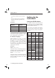
How to Measure Fast Speed Summary The following table summarizes the time that can be gained when fine tuning the measurement process. The normal dead time between frequency measurements is approximately as follows: 48.8 ms for the PM6680B. 85 ms for the PM6681. 75 ms for the PM6685. If you should read out the measuring result to the controller add read out time to each result. (Consult your controller manual.
How to Measure Fast S p e e d , In d iv id u a lly s y n c . m e a s u r e m e n ts P M 6 6 8 0 B S p e e d , In d iv id u a lly s y n c .
How to Measure Fast Block Synchronized Measurements (:ARM:STARt:LAYer:COUNt 1 and TRIG:COUNt ) Low resolution ([SENS]:ACQ:RES LOW) Realtime calculations OFF ([SENS]:INT:FORM PACK) CAL:INT:AUTO OFF Display OFF Speed Improvement Actions U U U U U + + U Dead Time Between Measurements PM6680B PM6681 PM6685 9 ms 4.5 ms 9 ms 2 ms 1.3 ms 2.5 ms 0.5 ms 0.12 ms 0.6 ms 0.5 ms 0.025 ms* 0.
How to Measure Fast S p e e d , B lo c k s y n c . m e a s u r e m e n ts P M 6 6 8 5 2 0 0 0 2 0 0 0 1 7 5 0 1 7 5 0 1 5 0 0 1 5 0 0 1 2 5 0 B lo c k d a ta , a ll 1 0 0 0 B lo c k d a ta , n o 7 5 0 5 0 0 2 5 0 1 2 5 0 B lo c k d a ta , a ll 1 0 0 0 B lo c k d a ta , n o 7 5 0 5 0 0 2 5 0 0 8 E -0 7 0 1 0 ,0 1 1 E -0 4 M e a s u r e m e n t T im e S p e e d , B lo c k s y n c .
How to Measure Fast Timesaving Commands Time Gain in ms PM6680B PM6681 PM6685 Freq FREQ:RANG:LOW8MAX Sacrifice Freq (23) Freq (23) 10kHz lower freq. limit for AUTO. This Timesaving is only possible when AUTO is on. 50kHz lower freq. limit for AUTO. This Timesaving is only possible when AUTO is on. (55) INP:LEV:AUTO8OFF 40 70 52 You have to set trigger levels manually. DISP:ENAB8OFF 5.4 3.5 7.7 Only the controller can read the result. CAL:INT:AUTO8OFF 0.22 N.A. 0.
How to Measure Fast Single “Speed Switch” Command for PM6680B/85 Single “Speed Switch” Command for PM6681 Since many parameters must be set to get the highest measuring speed, it is simpler if you use the macro function: Since many parameters must be set to get the highest measuring speed, it is simpler if you use the macro function: Send the following lines to turn on macros; define one macro called FASTFREQ and one macro called SLOWFREQ.
Chapter 8 Error Messages
Error Messages Read the Error/Event Queue empty, and the query will return: :SYSTem:ERRor? You read the error queue with the :SYS0, “No error” Tem:ERRor? query. Example: SEND→ :SYSTem:ERRor? READ← –100, “Command Error” When errors occur and you do not read these errors, the Error Queue may overflow. Then the instrument will overwrite the last error in the queue with: The query returns the error number fol–350, “Queue overflow” lowed by the error description.
Error Messages Command Errors Error Number Error Description Description/Explanation/Examples –105 GET not allowed –108 Parameter not allowed –109 Missing parameter –110 Command header error –111 Header separator error –112 Program mnemonic too long Undefined header A Group Execute Trigger was received within a program message (see IEEE-488.2, 7.7).
Error Messages Command Errors Error Number Error Description –121 Invalid character in number –123 –124 –128 –130 –131 –134 –138 –140 –141 –144 –148 –150 Description/Explanation/Examples An invalid character for the data type being parsed was encountered; for example, an alpha in a decimal numeric or a “0" in octal data. Exponent too large The magnitude of the exponent was larger than 32000 (see IEEE-488.2, 7.7.2.4.1).
Error Messages Command Errors Error Number Error Description Description/Explanation/Examples –151 Invalid string data Invalid string data; unexpected end of message String data not allowed Block data error A string data element was expected, but was invalid for some reason (see IEEE-488.2, 7.7.5.2); for example, an END message was received before the terminal quote character. –158 –160 –161 –168 –170 A string data element was encountered but was not allowed by PM6685 at this point in parsing.
Error Messages Command Errors Error Number Error Description Description/Explanation/Examples –171 Invalid expression data The expression data element was invalid (see IEEE-488.2, 7.7.7.2); for example, unmatched parentheses or an illegal character were used. A mnemonic data element in the expression was not valid. The expression contained a hexadecimal element not permitted in expressions. End of message occurred before the closing parenthesis.
Error Messages Execution errors Error Number Error Description description/explanation/examples –200 Execution error This is the generic syntax error for devices that cannot detect more specific errors. This code indicates only that an Execution Error as defined in IEEE-488.2, 11.5.1.1.5 has occurred.
Error Messages Execution errors Error Number Error Description description/explanation/examples –222 Data out of range Indicates that a legal program data element was parsed but could not be executed because the interpreted value was outside the legal range as defined by the counter (see IEEE-488.2, 11.5.1.1.5.). The expression was too large for the internal floating-point format. Data below minimum for this function/parameter.
Error Messages Execution errors Error Number Error Description description/explanation/examples –241 Hardware missing Hardware missing; (prescaler)" –254 Media full –258 Media protected –260 Expression error –261 Math error in expression –270 Macro error –271 Macro error; out of name space Macro error; out of definition space Macro syntax error Indicates that a legal program command or query could not be executed because of missing counter hardware; for example, an option was not installed
Error Messages Execution errors Error Number Error Description –273 Illegal macro label –274 –275 –276 –277 –278 description/explanation/examples Indicates that the macro label defined in the ∗DMC command was a legal string syntax, but could not be accepted by the counter (see IEEE-488.2, 10.7.3 and 10.7.6.2); for example, the label was too long, the same as a common command header, or contained invalid header syntax.
Error Messages Standardized Device specific errors Error Number Error Description description/explanation/examples –330 Device specific error This code indicates only that a Device-Dependent Error as defined in IEEE-488.2, 11.5.1.1.6 has occurred. Contact your local service center. Memory error Indicates that an error was detected in the counter’s memory. Contact your local service center. PUD memory lost Indicates that the protected user data saved by the ∗PUD command has been lost.
Error Messages Query errors Error Number Error Description description/explanation/examples –400 Query error –410 Query INTERRUPTED This code indicates only that a Query Error as defined in IEEE-488.2, 11.5.1.1.7 and 6.3 has occurred. Indicates that a condition causing an INTERRUPTED Query error occurred (see IEEE-488.2, 6.3.2.3); for example, a query was followed by DAB or GET before a response was completely sent. The additional information indicates the IEEE-488.
Error Messages CNT-8X Device specific errors (leading 1 only for PM6681) Error Number (1)100 (1)101 (1)102 (1)110 (1)120 (1)130 (1)131 (1)132 (1)133 (1)134 (1)135 (1)136 (1)137 (1)138 (1)139 Error Description description/explanation/examples Device operation gave floating-point underflow Device operation gave floating-point overflow Device operation gave ‘not a number’ A floating-point error occurred during a counter operation.
Error Messages CNT-8X Device specific errors (leading 1 only for PM6681) Error Number (1)150 (1)160 (1)170 (1)190 (1)191 (1)200 (1)201 (1)202 (1)203 (1)204 (1)205 (1)210 (1)211 (1)212 (1)213 Error Description description/explanation/examples Only a fixed, specific math expression is recognized by the counter, and this was not it. A new bus command caused a running measurement to be broken off. An internal setting inconsistency caused the instrument to go to default setting.
Error Messages CNT-8X Device specific errors (leading 1 only for PM6681) Error Number Error Description description/explanation/examples (1)220 Hash table overflow The hash table was too small to hold all mnemonics. Ordinarily indicates a failure to read (RAM or ROM) correctly. Contact your local service center. Parser error Generic error in the parser. (1)221 Illegal parser call (1)222 Unrecognized input A character not in the valid IEEE488.2 character set character was part of a command.
Error Messages This page is intentionally left blank.
Chapter 9 Command Reference
This page is intentionally left blank.
Abort :ABORt Command Reference 9-3
:ABORt PM6680B/81/85 Abort Measurement The ABORt command terminates a measurement. The trigger subsystem state is set to “idle-state”. Type of command: Aborts all previous measurements if *WAI is not used. Complies to standards: SCPI 1991.0, confirmed.
Arming Subsystem :ARM [ :STARt / :SEQuence [ 1 ] ] :LAYer2 :[ IMMediate ] :SOURce [ :LAYer [ 1 ] ] :COUNt :DELay :ECOunt :SLOPe :SOURce :STOP / SEQuence2 [ :LAYer [ 1 ] ] 8 BUS | IMMediate 8 | MIN | MAX 8 | MIN | MAX | MIN | MAX POSitive|NEGative EXTernal2 | External4 | IMMediate 8 8 8 8 :DELay :ECOunt :SLOPe :SOURce 8 8 8 | MIN | MAX (Only PM6680B / PM6681) | MIN | MAX (Only PM6680B / PM6681) POSitive | NEGative EXTer
:ARM :COUNt 8«|MIN|MAX» PM6680B/81/85 No. of Measurements on each Bus arm This count variable controls the upward exit of the “wait-for-bus-arm” state (:ARM:STARt:LAY1). The counter loops the trigger subsystem downwards COUNt number of times before it exits to the idle state. This means that a COUNt No. of measurements can be done for each Bus arming or INITiate.
:ARM :DELay PM6680B/81/85 8 « | MIN | MAX» Delay after External Start Arming This command sets a delay between the pulse on the arm input and the time when the counter starts measuring. The delay is only active when the following is selected: :ARM:STARt:SOURce 8 EXT4. Range: 200 ns to 1.67 s. + The optional node [:FIXed] is only accepted by PM6681. Parameters: is a number between 200*10–9 and 1.67s. MIN gives 0 which switches the delay OFF. MAX gives 1.
:ARM :LAYer2 PM6680B/81/85 Bus Arming Override This command overrides the waiting for bus arm, provided the source is set to bus. When this command is issued, the counter will immediately exit the “wait-for-busarm” state. The counter generates an error if it receives this command when the trigger subsystem is not in the “wait-for-bus-arm” state. If the Arming source is set to Immediate, this command is ignored. Example: SEND® :ARM:LAY2¿ Complies to standards: SCPI 1991.0, confirmed.
:ARM :SLOPe PM6680B/81/85 8 «POSitive|NEGative» External Arming Start Slope Sets the slope for the start arming condition. Returned format: POS|NEG¿ Example: SEND® :ARM:SLOP 8 NEG¿ *RST condition: POS Complies to standards: SCPI 1991.0, confirmed. :ARM :SOURce PM6680B/81/85 8 «EXTernal2 | EXTernal4 | IMMediate» External Arming Start Source Selects channel 4 (Input E) as arming input, or switches off the start arming function. When switched off the DELay is inactive.
:ARM :STOP :DELay 8 « | MIN | MAX» PM6680B PM6681 Delay after External Stop Arming This command sets a delay between stop slope of the pulse on the arm input and the time when the counter stops measuring. The delay is only active when the following is selected: :ARM:STOP:SOURce 8 EXT2|EXT4. Range: 200 ns to 1.67 s. + The optional node [:FIXed] is only accepted by PM6681. Parameters: is a number between 200*10–9 and 1.67s. MIN gives 0 which switches the delay OFF.
:ARM :STOP :SLOPe PM6680B/81/85 8 «POSitive | NEGative» External Stop Arming Slope Sets the slope for the stop arming condition. Returned format: POS|NEG¿ Example: SEND® :ARM:STOP:SLOP 8 NEG¿ *RST condition: POS Complies to standards: SCPI 1991.0, confirmed. :ARM :STOP :SOURce PM6680B/81/85 8 «EXTernal2 | EXTernal4 | IMMediate» External Stop Arming Source Selects between channel 2 (Input B) and channel 4 (Input E) as stop arming input, or switches off the stop arming function.
This page is intentionally left blank.
Calculate Subsystem :CALCulate 8 ON|OFF :STATe :DATA? :IMMediate :MATH 8 8 ON|OFF [:EXPRession] :STATe :AVERage :LIMit 8 ON|OFF 8 MIN|MAX|SDEViation|MEAN 8 |MIN|MAX [:STATe] :TYPE :COUNt [:STATe] 8 :UPPer :LOWer :FAIL? ON|OFF [:DATA] :STATe 8 |MIN|MAX 8 ON|OFF [:DATA] :STATe 8 |MIN|MAX 8 ON|OFF Command Reference 9-13
:CALCulate :AVERage :COUNt 8 < No. of samples> PM6680B PM6681 Sample Size for Statistics Sets the number of samples to use in statistics sampling. Parameters: is a number in the range of 1 to 65535. Returned format: < No. of samples>¿ *RST condition: 100 :CALCulate :AVERage :STATe 8 < Boolean > Enable Statistics PM6680B PM6681 Switches On/Off the statistical function. Note that the CALCulate subsystem is automatically enabled when the statistical functions are switched on.
:CALCulate :AVERage :TYPE PM6680B PM6681 8 «MAX|MIN|MEAN|SDEViation» Statistical Type Selects the statistical function to be performed. + You must use :CALC:DATA? to read the result of statistical operations. :READ?, :FETC? will only send the results that the statistical operation is based on. Parameters: MAX returns the maximum value of all samples taken under :CALC:AVER control. MIN returns the minimum value of all samples taken under :CALC:AVER control.
:CALCulate :IMMediate PM6680B/81/85 Recalculate Data This event causes the calculate subsystem to reprocess the statistical function on the sense data without reacquiring the data. Query returns this reprocessed data. + This command is not very useful in PM6685, but is accepted to maintain compatibility with the other counters in the CNT-8X series of counters. ¿ Where: is the recalculated data.
:CALCulate :LIMit :FAIL? PM6680B/81/85 Limit Fail Returns a 1 if the limit testing has failed (the measurement result has passed the limit), and a 0 if the limit testing has passed. The following events reset the fail flag: – Power-on – *RST – A :CALC:LIM:STAT OFF ® :CALC:LIM:STAT 8 ON transition – Reading a 1 with this command.
:CALCulate :LIMit :LOWer :STATe Calculate 8 PM6680B/81/85 Check Against Lower Limit Selects if the measured value should be checked against the lower limit. Parameters = ( 1/ON | 0/OFF ) Returned format: 1| 0 ¿ *RST condition: 0 Complies to standards: SCPI 1991.0 confirmed. :CALCulate :LIMit :UPPer 8 «|MAX|MIN» Set Upper Limit PM6680B/81/85 Sets the value of the ‘Upper Limit’, i.e.
:CALCulate :LIMit :UPPer :STATe PM6680B/81/85 8 Check Against Upper Limit Selects if the measured value should be checked against the upper limit. Parameters = ( 1/ON | 0/OFF ) Returned format: 1| 0 ¿ *RST condition: 0 Complies to standards: SCPI 1991.0, confirmed.
:CALCulate :MATH 8 () PM6685 Select Mathematical Expression Defines the mathematical expression used for mathematical operations. This function equals the nulling function from the front panel. + + The data type must be typed within parentheses. The operand must be surrounded by space characters. Parameters is: (X + K) No deviations are allowed from this form. K can be any positive or negative numerical constant within the range –9.9E+37 to +9.
:CALCulate :MATH PM6680B PM6681 8 () Select Mathematical Expression Defines the mathematical expression used for mathematical operations. This function equals the nulling function from the front panel. + The data type must be typed within parentheses. Parameters is one of the following two mathematical expressions: ((K8*_X)8+8L)8/8M or ((K8/8X)8+8L)8/8M No deviations are allowed.
:CALCulate :STATe PM6680B/81/85 Calculate 8 Enable Calculation Switches on/off the complete post-processing block. If disabled, neither mathematics or limit-monitoring can be done. Parameter = ( 1/ON | 0/OFF ) SEND® :CALC:STAT 8 1 Switches on Post Processing. Returned format: 1|0¿ ∗RST condition: OFF Complies to standards: SCPI 1991.
Calibration Subsystem :CALibration :INTerpolator :AUTO + 8 |ONCE (Only PM6680B, PM6685) PM6681 has factory calibrated interpolators, and calibration cannot be changed by the operator. Calibration of the PM6681 input hysteresis is done in the Diagnostis subsystem.
:CALibration :INTerpolator :AUTO 8 | ONCE PM6680B/85 Calibration of Interpolator The PM6680B/85 are reciprocal counters that uses an interpolating technique to increase the resolution. In time measurements, for example, interpolation increases the resolution from 100 ns to 0.25 ns. The counter calibrates the interpolators automatically once for every measurement when this command is ON.
Configure Function Set up Instrument for Measurement :CONFigure [:SCALar] :ARRay + 8 ,()] 8 ()[,,()] The array size for :MEASure and :CONFigure, and the channels, are expression data that must be in parentheses ( ). Measuring Function, Parameters and Channels are explained on page 9-54. The counter uses the default Parameters and Channels when you omit them in the command.
:CONFigure : [8 [,()]] PM6680B/81/85 Configure the counter for a single measurement Use the configure command instead of the measure query when you want to change other settings, for instance, the input settings before making the measurement and fetching the result. The :CONFigure command controls the settings of the Input, Sense and Trigger subsystems in the counter in order to make the best possible measurement.
80B/81/85 :CONFigure :ARRay : 8 ()[, [,()]] Configure the counter for an array of measurements The :CONFigure:ARRay command differs from the :CONFigure command in that it sets up the counter to perform the number of measurements you choose in the . To perform the selected function, you must trigger the counter with the :READ:ARRay? or :INITiate;:FETCh:ARRay? queries.
This page is intentionally left blank.
Diagnostics Subsystem :DIAGnostic :CALibration :INPut[1] :INPut2 :HYSTeresis 8 OFF | ONCE :HYSTeresis 8 OFF | ONCE Command Reference 9-29
:DIAGnostic:CALibration:INPut[1|2]:HYSTeresis 8 «OFF | ONCE» 81 Fetch Input comparator hysteresis calibration These two commands measure and save the hysteresis levels of the input comparator. This makes it possible to achieve a trig level accuracy of 2.5 mV, which is important in measurement functions such as phase, to get the best possible results.
Display Subsystem :DISPlay :ENABle 8 ON OFF Command Reference 9-31
:DISPlay :ENABle 8 < Boolean > PM6680B/81/85 Display State Turns On/Off the updating of the entire display section. This can be used for security reasons or to improve the GPIB speed, since the display does not need to be updated. Turning off the display reduces the dead time between measurements by about 7 ms. When the display is turned off, the information about the measurement resolution is lost. That is, the counter will always send a full 12 digit mantissa independent of the measurement resolution.
Fetch Function :FETCh [:SCALar]? :ARRay? 8 |MAX Command Reference 9-33
:FETCh? PM6680B/81/85 Fetch One Result The fetch query retrieves one measuring result from the measurement result buffer of the counter without making new measurements. Fetch does not work unless a measurement has been made by the :INITiate, :MEASure?, or :READ? commands. If the counter has made an array of measurements, :FETCh? fetches the first measuring results first. The second :FETCh? fetches the second result and so on.
:FETCh :ARRay? PM6680B/81/85 8 «|MAX» Fetch an Array of Results :FETCh:ARRay? query differs from the :FETCh? query by fetching several measuring results at once. An array of measurements must first be made by the commands. :INITiate, :MEASure:ARRay? or :CONFigure:ARRay;:READ? If the array size is set to a positive value, the first measurement made is the first result to be fetched.
[,]¿ The format of the returned data is determined by the format commands :FORMat and :FORMat:FIXed. Returned format: Example: If :MEAS:ARR:FREQ? 8 (4) gives the results 1.1000,1.2000,1.3000,1.4000 :FETC:ARR 8 2 fetches the results 1.1000,1.2000 :FETC:ARR 8 2 once more fetches the results 1.3000,1.4000 :FETC:ARR 8 –1 always fetches the last result 1.4000 Complies to standards: SCPI 1991.0, confirmed.
Format Subsystem :FORMat [:DATA] :FIXed :SREGister :TINFormation[:STATe] 8 8 8 8 ASCii REAL[, | AUTO] ON OFF ASCii | BINary | HEXadecimal | OCTal Command Reference 9-37
:FORMat PM6680B/85 8 «ASCii|REAL» Response Data Type Sets the format in which the result will be sent on the bus. Parameters ASCii will send the measurement result in ASCii form.E = + or – = 1 to 12 digits (depending on measuring resolution) plus one decimal point. = 1 to 3 digits REAL will send the result in binary IEEE Double Precision floating-point format in a block-data element. #18<8 bytes real>.
:FORMat :FIXed PM6680B/81/85 8 Response Data Format Sets the ASCii format to fixed. This results in the following response format: E Where: = +|– = 12 digits plus one decimal point. = 3 digits Parameters + = (1 / ON | 0 / OFF) The counter will add leading zeroes when the measurement resolution is less than 12 digits.
:FORMat :TINFormation 8 Boolean PM6681 Timestamping On/Off Timestamping;On/Off This command turns on/off the time stamping of measurements. Time stamping is always done at the start of a measurement with a resolution of 125 ns, and is saved in the measurement buffer together with the measurement result. The setting of this command will affect the output format of the MEASure, READ and FETCh queries.
Initiate Subsystem :INITiate [:IMMediate ] :CONTinuous 8 ON | OFF Command Reference 9-41
:INITiate PM6680B/81/85 Initiate Measurement The :INITiate command initiates a measurement. Executing an :INITiate command changes the counter’s trigger subsystem state from “idle-state” to “wait-for-bus-arm-state” (see Figure 6-15). The trigger subsystem will continue to the other states, depending on programming. With the *RST setting, the trigger subsystem will bypass all its states and make a measurement, then return to idle state.
Input Subsystems n INPUT A :INPut[1] :ATTenuation :COUPling :IMPedance [:EVENt] :HYSTeresis :LEVel :SLOPe :FILTer :AUTO :AUTO [:LPASs] [:STATe] 8 |MIN|MAX (1|10) 8 AC|DC 8 |MIN|MAX (Not PM6685) (Not PM6685) «|MAX |MIN» ON|OFF|ONCE |MIN|MAX ON|OFF|ONCE POS|NEG (Only PM6685) (Only PM6685) 8 8 8 8 8 8 ON|OFF n INPUT B (Not PM6685) :INPut2 8 |MIN|MAX (1|10) 8 AC|DC 8 |MIN|MAX :ATTenuation :COUPling :IMPedance [:E
:INPut«[1]|2» :ATTenuation 8 «|MAX|MIN» PM6680B PM6681 Attenuation Attenuates the input signal with 1 or 10. The attenuation is automatically set if the input level is set to AUTO. Parameters: â 5, and MIN gives attenuation 1. > 5, and MAX gives attenuation 10. Returned format: 1.00000000000E+000|1.
:INPut :FILTer PM6680B/81/85 8 Low Pass Filter Switches on or off the low pass filter on input 1 (A). It has a cutoff frequency of 100 kHz. Parameters: is (1 / ON | 0 / OFF) Returned format: *RST condition 1|0¿ OFF Complies to standards: SCPI 1991.0, confirmed. :INPut :HYSTeresis PM6685 8 «|MAX |MIN» Sensitivity The sensitivity setting on the front panel is called HYSTeresis from the bus. The range is 27.12 mV to 75.4 V.
:INPut :HYSTeresis :AUTO 8 «|ONCE» PM6685 Auto Sensitivity AUTO from the front panel turns on both auto sensitivity (hysteresis) and auto waveform compensation(trigger level). From the bus there are two commands, one for auto hysteresis and one for auto trigger level. However, the function of these commands are identical. Both commands turn on/off the hysteresis and the trigger level simultaneously. The auto sensitivity function normally sets the hysteresis to 33% of Vpp.
:INPut«[1]|2» :IMPedance PM6680B/81/85 8 «|MAX|MIN» Input Impedance The impedance can be set to 50 W or 1 MW. Parameters MIN or that rounds off to 50 or less, sets the input impedance to 50 MAX or that rounds off to 1001 or more, sets the impedance to 1 MW. Returned format: 5.00000000000E+001|1.00000000000E+6¿ Example for Input A (1) SEND® :INP:IMP 8 50 Sets the input A impedance to 50 W.
:INPut :LEVel 8 «|MAX|MIN» PM6685 Waveform compensation The three-position waveform compensation on the front panel is not available from the bus. Instead, you can set the trigger level, that is, the level on which the hysteresis band is centered. How to set the trigger level depends on the duty cycle and the peak-to-peak voltage of the signal. Trigger level = Vpp * (0.5 - Duty factor ) This setting has no effect unless autosensitivity is turned off, see the following page.
PM6680B PM6681 :INPut :LEVel :AUTO 8 «|ONCE» Autotrigger If set to AUTO, the counter automatically controls both the trigger level and the attenuation1. If you have a stable amplitude, use the :AUTO 8 ONCE, and the autotrigger will determine the trigger level once and then set a fixed level. + From the bus, input A and input B are always set to autotrigger individually.
:INPut :LEVel :AUTO 8 «|ONCE» PM6685 Autotrigger :INPut:AUTO? If auto is on, the counter automatically controls the trigger level1 and the hysteresis. If you have a stable amplitude, use the :AUTO ONCE, and auto will determine the trigger level once, and then set fixed levels. Parameters = ( 1/ON | 0/OFF ) ONCE means that AUTO first switches ON to check the signal.
:INPut«[1]|2|4» :SLOPe PM6680B/81/85 8 «POS|NEG» Trigger Slope Selects if the counter should trigger on a positive or a negative transition. Selecting negative slope is useful when measuring negative pulse width and negative duty cycle. When you select negative slope, the counter always uses the non-prescaled mode, limiting the maximum input frequency to 160 MHz.
This page is intentionally left blank.
Measurement Function Set up the Instrument, Perform Measurement, and Read Data :MEASure [:SCALar]? [][,()] :ARRay? :MEMory? 8 ()[,][,()] [] :MEMory? + The array size for :MEASure and :CONFigure, and the channels, are expression data that must be in parentheses ( ).
:MEASure|:CONFigure [:VOLTage] [:SCALar] :FREQuency [:CW]? PM6680B PM6681 [ _ [[,],][(@1|@2|@3|@4|@5|@6|@7)]] :RATio? [ _ [[,],][(@1|@2|@3|@4),(@1|@2|@3|@4)]] :BURSt? [ _ [[,],][(@1|@2|@3|@4|@5|@6|@7)]] :PRF? [ _ [[,],][(@1|@2|@3|@4|@5|@6|@7)]] :PERiod? [ _ [[,],][(@1|@2|@3|@4|@5|@6|@7)]] :TINTerval? [ _ [[,],][(@1|@2|@4),(@1|@2|@4)]] :PHASe? [ _ [[,
PM6685 :MEASure|:CONFigure [:VOLTage] [:SCALar] :FREQuency [[,]][,(@1|@3|@4|@5|@6)]] :RATio? [ 8 [[,
:MEASure :? [8 [][ ,()]] PM6680B/81/85 Make one measurement The measure query makes a complete measurement, including configuration and readout of data. Use measure when you can accept the generic measurement without fine tuning. + When a CONFigure command or MEASure? query is issued, all counter settings are set to the *RST settings., except those specified as and in the CONFigure command or MEASure? query.
80B/81/85 :MEASure :ARRay :? [ 8 ()[,[] [,()]] Make an array of measurements The :MEASure:ARRay query differs from the :MEASure query in that it performs the number of measurements you decide in the and sends all the measuring results in one string to the controller. + The array size for :MEASure and :CONFigure, and the channels, are expression data that must be in parentheses ( ).
:MEASure:MEMory? PM6681 Memory Recall, Measure and Fetch Result Use this command when you want to measure several parameters fast. :MEAS:MEM1? recalls the contents of memory 1 and reads out the result, :MEAS:MEM2? recalls the contents of memory two and reads out the result etc. The equivalent command sequence is *RCL1;READ? The allowed range for is 1 to 9. Use the somewhat slower :MEAS:MEMory? N command described below if you must use memories 10 to 19.
EXPLANATIONS OF THE MEASURING FUNCTIONS This sub-chapter explains the various measurements that can be done with :MEASure and :CONFigure;:READ. Only the queries for single measurements using the measure command are given here, but all of the information is also valid for the :CONFigure command and for both scalar (single) and array measurements. PM6680B/81/85 :MEASure_«:DCYCle/:PDUTycycle» [8 [] [,(@«1|2|4|6»)]] Positive Duty Cycle Traditional duty cycle measurement is performed.
:MEASure :FREQuency? [8 [[,]] [,<(@«1|2|3|4|5|6|7»)>]] PM6680B/81/85 Frequency Traditional frequency measurements. The counter uses the and to calculate the Measurement Time (:SENSe:ACQuisition:APERture). Example: SEND® :MEAS:FREQ? 8 (@3) READ¬ 1.78112526833E+009 This example measures the frequency at input C. + The channel is expression data and it must be in parentheses ( ).
PM6680B/81/85 :MEASure :FREQuency :BURSt? [8 [[,]] [,<(@«1|2|3|4|5|6|7»)>]] Burst Carrier Frequency Measures the carrier frequency of a burst. The burst duration must be less than 50% of the pulse repetition frequency (PRF). How to measure bursts is described in detail in the Operators Manual. The counter uses the and to select a Measurement Time ([:SENSe]:ACQuisition:APERture), and then sets the sync delay ([:SENSe]:SDELay) to 1.
:MEASure :FREQuency :PRF? [8 [[,]][,<(@«1|2|3|4|5|6|7»)>]] PM6680B/81/85 Pulse Repetition Frequency Measures the PRF (Pulse Repetition Frequency) of a burst signal.The burst duration must be less than 50% of the pulse repetition frequency (PRF). + It is better to set up the measurement with the [:SENS]:FUNC “:FREQ:PRF” command when measuring pulse repetition frequency. This command will allow you to set a suitable sync delay with the [:SENSe]:Sync:DELay command.
PM6680B PM6681 :MEASure :FALL :TIME? [8 [ [,[,[,]]]] [,(@1)]] Fall-time The transition time from 90% to 10% of the signal amplitude is measured. The measurement is always a single measurement and the Auto-trigger is always on, setting the trigger levels to 90% and 10 % of the amplitude. If you need an average transition time measurement, or other trigger levels, use the :SENSe subsystem and manually set trigger levels instead.
:MEASure [:VOLT] :MAXimum? [ 8 («@1|@2»)] PM6680B PM6681 Positive Peak Voltage This command measures the positive peak voltage with the input DC coupled. Parameters: («@1|@2») is the channel to measure on (@1) means input A (@2) means input B Complies to standards: SCPI 1991.0, confirmed.
:MEASure :NWIDth? PM6680B/81/85 [8 [] [,<(@«1|2|4|6»)>]] Negative Pulse Width A negative pulse width measurement is performed. This is always a single measurement. If you need an average pulse width measurement, use the :SENSe subsystem instead. Parameters parameter sets the trigger levels in volts. If omitted, the auto trigger level is set to 50 percent of the signal.
:MEASure_«:PDUTycycle/ :DCYCle»? [8 [] [,(@«1|2|4|6»)]] PM6680B/81/85 Positive duty cycle: Duty Factor Traditional duty cycle measurement is performed. That is, the ratio between the on time and the off time of the input pulse is measured. Parameters parameter sets the trigger levels in volts. If omitted, the auto trigger level is set to 50 percent of the signal.
PM6680B/81/85 :MEASure :PERiod? [8 [ [,]][,<(@«1|2|3|4|5|6|7»)>]] Period A traditional period measurement is performed. The and are used to calculate the Measurement Time ([:SENSe]:ACQuisition:APERture).
:MEASure [:VOLT] :PTPeak? [8 (@«1|2»)]. PM6680B PM6681 Peak-to-Peak Voltage This command make measures the peak-to-peak voltage with the input DC coupled. Parameters: (@«1|2») is the channel to measure on (@1) means input A (@2) means input B Complies to standards: SCPI 1991.0, confirmed. :MEASure :RISE :TIME? PM6680B PM6681 [8 [ [,[,[,]]]] [,(@1)] Rise-time The transition time from 10% to 90% of the signal amplitude is measured.
PM6680B PM6681 :MEASure :TINTerval? 8 (@«1|2|4»),(@«1|2|4»)] Time-Interval Traditional time-interval measurements are performed. The trigger levels are set automatically, and positive slope is used. The first channel in the channel list is the start channel, and the second is the stop channel.
:MEASure :TOTalize :ACCumulated? [8
:CONFigure :TOTalize :CONTinuous PM6680B/81/85 [8 (@«1|2|4|6»)][,(@«1|2|4|6»)] Totalize Manually This is a count/totalize function controlled from the GPIB interface using the command SENS:TOT:GATE8ON|OFF. The counter counts up for each event on the primary input channel. and down on the secondary channel. The result is the difference between the primary and secondary channel. In addition to selecting totalizing, the :CONF:TOT:CONT command also selects positive trigger slope.
:MEASure :TOTalize :GATed? [8 (@«1|2|4|5|6») [,(@«1|2|4|5|6»)]] PM6680B PM6681 Totalize X gated by Y The counter totalizes the pulses on the primary channel. The totalizing starts when the gate signal on the secondary channel goes on and stops when the gate signal goes to off. The polarity of on/off is controlled via the :INPut:SLOPe command of the gate signal. Select if the counter should count positive or negative transitions with the :INPut:SLOPe command of the measuring channel.
PM6680B PM6681 :MEASure :TOTalize :TIMed? [8 [
This page is intentionally left blank.
Memory Subsystem :MEMory :DELete :FREE :MACRo 8 ‘’ :SENSe? :NSTates? :MACRo? Related Common Commands: *DMC *EMC *GMC? *LMC? *LRN? *PMC *RCL *RMC *SAV Command Reference 9-75
:MEMory :DELete :MACRo 8 ‘’ PM6680B/81/85 Delete one Macro This command removes an individual MACRo1. Parameters ‘’ is the name of the macro you want to delete. + is String data that must be surrounded by quotation marks. See also: *PMC, if you want to delete all macros. 1 The proposed IEEE488.2 command *RMC (Remove Macro command) also works on PM6685. It preforms exactly the same action as :MEMory:DELete:MACRo.
:MEMory :FREE :MACRo? PM6680B/81/85 Memory Free for Macros This command gives information of the free memory available for MACRos in the counter. If no macros are specified, 1160 bytes are available. Returned format: , ¿ Complies to standards: SCPI 1991.0, confirmed. :MEMory :NSTates? PM6680B/81/85 Memory States The Number of States query (only) requests the number of *SAV/ ∗RCL instrument setting memory states available in the counter.
This page is intentionally left blank.
Output Subsystem :OUTPut [:STATe] :SCALe 8 ON | OFF 8 Command Reference 9-79
:OUTPut PM6680B/81/85 8 Enable Analog Out This command switches on/off the analog output. See also :OUTput:SCALe command on the next page. Parameters = ( 1/ON | 0/OFF ) Returned format: <1|0>¿ Example: Send® :OUTP 8 1 Switches on the analog output. *RST condition: OFF Complies to standards: SCPI 1991.0 confirmed. :OUTPut :SCALe 8 < Decimal data > PM6680B/81/85 Scaling Factor, Analog Output This command sets the scaling factor for the analog output.
Read Function Perform Measurement and Read Data :READ [:SCALar]? :ARRay? 8 |MAX Command Reference 9-81
:READ? PM6680B/81/85 Read one Result The read function performs new measurements and reads out a measuring result without reprogramming the counter. Using the :READ? query in conjunction with the :CONFigure command gives you a measure capability where you can fine tune the measurement. If the counter is set up to do an array of measurements, :READ? makes all the measurements in the array, stores the results in the output buffer, and fetches the first measuring result.
:READ:ARRay? PM6680B/81/85 8 «|MAX» Read an array of results The :READ:ARRay? query differs from the :READ? query by reading out several results at once after making the number of measurements previously set up by :CONFigure:ARRay 8 or 8 :MEASure:ARRAy?. The :READ:ARRay? query is identical to: :ABORt;:INITiate;:FETCh:ARRay?_ + The does not tell :READ to make that many measurements, only to fetch that many results.
This page is intentionally left blank.
Sense Command Subsystem n Sense Subsystem command tree for PM6680B and PM6681 [:SENSe] :ACQuisition :APERture :HOFF [:STATe] :ECOunt :MODE :TIME :RESolution :AVERage :COUNt :STATe :FREQuency :RANGe :FUNCtion :INTernal :LOWer :FORMat :ROSCillator :SOURce :TOTalize :GATE :VOLTage [:STATe] :GATed :STATe 8 | MIN | MAX 8 8 8 8 8 ON | OFF | MIN | MAX TIME | EVENt | MIN | MAX HIGH | LOW 8 | MIN | MAX 8 TIME | COUNts 8 ON|OFF
n Sense Subsystem command tree for PM6685 [:SENSe] 8 ‘Measuring function [_ Primary channel [ , Secondary channel ] ] ‘ :FUNCtion :EVENt1 :LEVel :AUTO :HYSTeresis :AUTO :SLOPe :ACQuisition :APERture :HOFF2 :AVERage :TIME :STATe :ROSCillator :SOURce :SDELay :TOTalize :GATE :INTernal [:STATe] :FORMat 8 8 8 8 8 | MIN | MAX ON | OFF | ONCE | MIN | MAX ON | OFF | ONCE POS | NEG 8 | MIN | MAX 8 | MIN | MAX 8 ON | OFF
:ACQuisition :APERture PM6680B/85 8 « |MIN|MAX» Set the Measurement Time Sets the gate time for one measurement. is 0.8E–6, 1.6E–6, 3.2E–6, 6.4E–6, or 12.8E–6 and 50E–6 to 400s. MIN gives 800 ns and MAX gives 400 s. Measurement Times of 800 ns to 12.8 ms work in :FREQ:CW, FREQ:BURST, :FREQ:PRF, 8 :FREQ:RAT and :PERiod. If one of these short times is selected when the counter makes other measurements, it will use 50 ms.
:ACQuisition :HOFF 8 PM6680B PM6681 Hold Off On/Off Switches the Hold Off function On/Off. Parameters: = 1 / ON | 0 / OFF Returned format: 1 | 0¿ *RST condition: OFF :ACQuisition :HOFF: ECOunt 8 «|MIN|MAX» Hold Off, set event counter PM6680B PM6681 Sets the Hold Off event value. The counter counts negative events on the B input (channel 2). Parameters: is a number in the range 2 to 16 777 215.
PM6680B PM6681 :ACQuisition :HOFF :MODE 8 «TIME|EVENt» Hold Off Mode Selects if triggering is going to be disabled for a preset time or for a preset number of events. When set to event, the counter counts negative edges on the B input (channel 2). This function is coupled to the :ARM:START:DEL, :ARM:START:ECO, :ARM:STOP:DEL and :ARM:STOP:ECO. The different delays must all be of the same type, (Time or Event). This means that setting one of them to Event delay causes the others to be set to Event delays.
:ACQuisition :RESolution 8 «HIGH|LOW» PM6680B Resolution Selects basic measurement mode for all time-related measurements. Parameters: HIGH: The resolution is the full 0.25 ns LOW: The resolution is limited to a 100-ns clock. You can use this to increase the bus speed. Saves about 0.6 to 0.9 ms if the counter does real-time calculations, otherwise, only 0.05 ms.
PM6680B PM6681 :AVERage :COUNt 8 «|MIN| MAX» Average Samples Sets the number of samples to use when doing time-interval averaging measurements in :AVER:MODE 8 COUN. Applies to the functions: PWIDTH, TIME, RISE and FALL TIME. Parameters: is a number between 1and 65535.
:AVERage :STATe PM6680B/81/85 8 Average or Single? Switch on/off the average function. Parameters: = 1 | ON / 0 | OFF ON means multiple period measurements for period related measurements and time-interval average for Time-Interval measurements. OFF means that the counter measures on a single cycle. This is the same as when pressing the SINGLE key on the front panel.
PM6680B/81/85 :FUNCtion 8 ‘[_ [,]]’ Select Measuring Function Selects which measuring function is to be performed and on which channel(s) the instrument should measure. Parameters: is the function you want to select, according to the SENSe subsystem command trees on page 9-85 and page 9-86. is the channel used in all single-channel measurements and the main channel in dual-channel measurements.
n Functions and channels in PM6680B and PM6681 :FREQuency :FREQuency :FREQuency :FREQuency [ :CW ] [ :CW ] :RATio :BURSt :PRF [8 [8 [8 [8 ‘(1|23|4|5|6|7)‘] ‘1|2|3|4,1|2|3|4‘] ‘1|2|3|4|5|6|7‘] ‘1|2|3|4|5|6|7‘] :PERiod [8 ‘1|2|3|4|5|6|7‘] :TINTerval :PHASe [8 [8 ‘1|2|4,1|2|4|6‘] ‘1|2|6,1|2|6‘] :NWIDth :PWIDth [8 [8 ‘1|2|4|6‘] ‘1|2|4|6‘] :DCYCle | PDUTycycle :NDUTycycl [8 [8 ‘1|2|4|6‘] ‘1|2|4|6‘] :RISE:TIME :FALL:TIME [8 [8 ‘1|2‘] ‘1|2‘] :VOLT:MAXimum :VOLT:MINimum :VOLT:PTPeak [8 [8 [8 ‘1
:INTernal :FORMat PM6680B/81/85 «REAL|PACKed» Internal Format This command selects the internal data format of the measurement result from the SENSe block. The purpose of the command is to increase the measurement speed. Parameters: REAL means that the result is calculated in real-time after each measurement. PACKed means that the raw measurement data is stored internally and the result is not calculated in real-time between measurements.
:ROSCillator :SOURce 8 «INT|EXT» PM6680B/81/85 Select Reference Oscillator Selects the signal from the external reference input as timebase instead of the internal timebase oscillator. Returned format: ¿ *RST condition: INT Complies to standards: SCPI 1991.0, confirmed. :SDELay 8 «|MIN|MAX» BURST/PRF Synchronization Delay PM6685 Sets the synchronization delay time used in FREQuency:BURSt | PRF measurements. Parameter range: 200 ns to 1.
:TOTalize :GATE PM6680B/81/85 8 Gate On/Off Open/closes the gate for :TOTalize[:CONTinuous]. + Before opening the gate with this command, the counter must be in the ‘continuously initiated’ state , (:INIT:CONT 8 ON)or else the totalizing will not start.
This page is intentionally left blank.
Status Subsystem :STATus :DREGister0 :ENABle [:EVENt]? 8 :OPERation :CONDition? :ENABle [:EVENt]? 8 :QUEStionable :CONDition? :ENABle [:EVENt]? 8 :PRESet n Related Common Commands: *CLS *ESE *ESR? *PSC *SRE *STB? 8 8 8 Command Reference 9-99
:STATus :DREGister0? 80B/81/85 Read Device Status Event Register This query reads out the contents of the Device Event Register. Reading the Device Event Register clears the register. See Figure 6-14. Returned format: = the sum (between 0 and 6) of all bits that are true. See table below: Bit No. Weight Condition 2 4 Last measurement below low limit. 1 2 Last measurement above high limit.
:STATus :OPERation :CONDition? 80B/81/85 Read Operation Status Condition Register Reads out the contents of the operation status condition register. This register reflects the state of the measurement process. See figure below. Note that bits 0 to 3, 7, and 9 to 15 are not used. Returned Format: = the sum (between 0 and 368) of all bits that are true. See table below: Bit No.
:STATus :OPERation :ENABle 80B/81/85 8 Enable Operation Status Reporting Sets the enable bits of the operation status enable register. This enable register contains a mask value for the bits to be enabled in the operation status event register. A bit that is set true in the enable register enables the corresponding bit in the status register. See figure on page 9-101. An enabled bit will set bit #7, OPR (Operation Status Bit), in the Status Byte Register if the enabled event occurs.
:STATus:OPERation? 80B/81/85 Read Operation Status, Event Reads out the contents of the operation event status register. Reading the Operation Event Register clears the register. See figure on page 9-101. Returned Format: ¿ = the sum (between 0 and 368) of all bits that are true. See table on page 9-102. Complies to standards: SCPI 1991.0, confirmed.
:STATus :QUEStionable :CONDition? PM6680B/81/85 Read Questionable Data/Signal Condition Register Reads out the contents of the status questionable condition register. Returned Format: = the sum (between 0 and 17920) of all bits that are true. See table below: Bit No. Weight Condition 14 16384 Unexpected parameter 10 1024 Timeout or no signal detected 9 512 Overflow Complies to standards: SCPI 1991.0, confirmed.
:STATus :QUEStionable :ENABle PM6680B/81/85 8 Enable Questionable Data/Signal Status Reporting Sets the enable bits of the status questionable enable register. This enable register contains a mask value for the bits to be enabled in the status questionable event register. A bit that is set true in the enable register enables the corresponding bit in the status register. See figure on page 9-104.
This page is intentionally left blank.
System Subsystem :SYSTem :COMMunicate :GPIB :ERRor? :ADDRess :PRESet :SYSTem:SDETect[:ENABle] :SET :TIME 8 | MIN | MAX 8 ON | OFF 8 (Only PM6685) :ELAPsed? :TOUT [:STATe] :TIME :UNPRotect 8 ON | OFF 8 :VERSion? n Related common command: *IDN? *OPT? *PUD *RST 8 Command Reference 9-107
:SYSTem :COMMunicate: GPIB: ADDRess 8 «|MAX|MIN» [,«|MAX|MIN»] 80B/81/85 Set GPIB Address This command sets the GPIB address. This selection overrides the switches on the rear panel of the counter. The set address is valid until a new address is set, either by bus command, switch setting, or via the front panel AUX-MENU. Parameters: is a number between 0 and 30. MIN sets address 0. MAX sets address 30. [,|MAX|MIN] sets a secondary address.
:SYSTem :PRESet PM6680B/81/85 Preset This command sets the counter to the same default settings as when the front panel key LOCAL/PRESET is pressed in local mode. + See also: These are not exactly the same settings as after *RST, SYST:PRES gives 200 ms Measurement Time and signal detection ON, while *RST gives 10-ms Measurement Time and signal detection OFF. Default settings on page -. Complies to standards: SCPI 1991.0, confirmed.
:SYSTem :SET PM6680B/81/85 8 Read or Send Settings Transmits in binary form the complete current state of the instrument. This data can be sent to the instrument to later restore this setting. This command has the same function as the *LRN? common command with the exception that it returns the data only as response to :SYST:SET?. The query form of this command returns a definite block data element.
:SYSTem :TOUT PM6680B/81/85 8 Timeout On/Off This command switches on or off the timeout. When timeout is enabled, the measurement attempt will be abandoned when the time set with :SYST:TOUT:TIME has elapsed. A zero result will be sent to the controller instead of a measurement result and the timeout bit in the STATus QUEStionable register will be set. 0 means no timeout; 1 means that the timeout set by :SYSTem:TOUT:TIME is used. Returned format: Example: SEND® :SYST:TOUT 8 1;TOUT:TIME 8 0.
:SYSTem :UNPRotect PM6680B/81/85 Unprotect This command will unprotect the user data (set/read by *PUD) and front setting memories 10-19 until the next PMT (Program message terminator) or Device clear or Reset (*RST). This makes it necessary to send an unprotect command in the same message as for instance *PUD. Example Send ® :SYST:UNPR; *PUD 8 #240Calibrated 8 1992-11-17, 8 inventory No.1234 Where: # means that will follow.
Test Subsystem :TEST :CHECk :SELect 8 ON | OFF 8 RAM | ROM | LOGic | DISPlay | ALL n Related common command: *TST Command Reference 9-113
:TEST:CHECk 8 PM6680B/81/85 Select Check signal This command connects the internal reference signal to the measuring logic, instead of an external measuring signal. This makes it possible to test all functions. The frequency of the reference is 10 MHz for PM6680B and PM6685, and 100 MHz for PM6681. Parameters: = 1 / ON | 0 / OFF 1 and ON means test signal connected 0 and OFF means test signal disconnected.
Trigger Subsystem :TRIGger [ STARt / :SEQuence [ 1 ] ] [ :LAYer [ 1 ] ] :COUNt 8 | MIN | MAX n Related common command: *TRG Command Reference 9-115
:TRIGger:COUNt 8 « | MIN | MAX» PM6680B/81/85 No. of Triggerings on each Ext Arm start Sets how many measurements the instrument should make for each ARM:STARt condition, (block arming). These measurements are done without any additional arming conditions before the measurement. This also means that stop arming is disabled for the measurements inside a block.
Common Commands *CLS *DMC *EMC *ESE *ESR? *GMC? *IDN? 8 , 8 8 8 *LMC? *LRN? *OPC *OPC? *OPT? *PMC *PSC *PUD *RCL *RMC *RST *SAV *SRE *STB? 8 8 8 8 8 8 *TRG *TST? *WAI Command Reference 9-117
*CLS PM6680B/81/85 Clear Status Command The *CLS common command clears the status data structures by clearing all event registers and the error queue. It does not clear enable registers and transition filters. It clears any pending *WAI, *OPC, and *OPC?. Example: Send ® *CLS Complies to standards: IEEE 488.2 1987.
*DMC PM6680B/81/85 8 , Define Macro Allows you to assign a sequence of one or more program message units to a macro label. The sequence is executed when the macro label is received as a command or query. Twenty five macros can be defined at the same time, and each macro can contain an average of 40 characters. If a macro has the same name as a command, it masks out the real command with the same name when macros are enabled.
*EMC PM6680B/81/85 8 Enable Macros This command enables and disables expansion and execution of macros. If macros are disabled, the instrument will not recognize a macro although it is defined in the instrument. (The Enable Macro command takes a long time to execute.) Parameters: = is 0 or 1. A value which rounds to 0 turns off macro execution. Any other value turns macro execution on.
*ESE PM6680B/81/85 8 Standard Event Status Enable Sets the enable bits of the standard event enable register. This enable register contains a mask value for the bits to be enabled in the standard event status register. A bit that is set true in the enable register enables the corresponding bit in the status register. An enabled bit will set the ESB (Event Status Bit) in the Status Byte Register if the enabled event occurs. See also status reporting on page 3-14. Parameters:
∗ESR? PM6680B/81/85 Event Status Register Reads out the contents of the standard event status register. Reading the Standard Event Status Register clears the register. Returned Format: = the sum (between 0 and 255) of all bits that are true. See table on page 9-121. Complies to standards: IEEE 488.2 1987. *GMC? PM6680B/81/85 8 < macro label> Get Macro Definition This command makes the counter respond with the current definition of the given macro label.
*IDN? PM6680B/81/85 Identification query Reads out the manufacturer, model, serial number, Firmware level for main and GPIB program in an ASCii response data element. The query must be the last query in a program message. Response is , , , . is not implemented in PM6680B and PM6685 and will always return a zero. Please look at the type plate at the rear panel of the counter if you are interested in the serial number.
*LRN? PM6680B/81/85 Learn Device Setup Learn Device Setup Query. Causes a response message that can be sent to the instrument to return it to the state it was in when the *LRN? query was made. Returned Format: :SYST:SET_¿ Where: is #292<92 data bytes> for PM6680B is #3104<104 data bytes> for PM6681 is #276<76 data bytes> for PM6685 Example SEND® *LRN? Complies to standards: IEEE 488.2 1987.
*OPC? PM6680B/81/85 Operation Complete Query Operation Complete query. The Operation Complete query places an ASCii character 1 into the device’s Output Queue when all pending selected device operations have been finished. Returned Format: 1¿ See also: Example 6 is Chapter 4. Complies to standards: IEEE 488.2 1987. *OPT? PM6680B/81/85 Option Identification Response is a list of all detectable options present in the instrument, with absent options represented with an ASCii ‘0’.
*PMC PM6680B/81/85 Purge Macros Removes all macro definitions. Example: *PMC See also: :MEMory:DELete:MACRo 8 ‘’ if you want to remove a single macro. Complies to standards: IEEE 488.2 1987. *PSC PM6680B/81/85 8 Power-on Status Clear Enables/disables automatic power-on clearing. The status registers listed below are cleared when the power-on status clear flag is 1. Power-on does not affect the registers when the flag is 0.
*PUD PM6680B/81/85 8 Protected User Data Protected user data. This is a data area in which the user may write any data up to 64 characters. The data can always be read, but you can only write data after unprotecting the data area. A typical use would be to hold calibration information, usage time, inventory control numbers, etc.
∗RMC PM6680B/81/85 8 ‘’ Delete one Macro This command removes an individual MACRo. Parameters: ‘’ is the name of the macro you want to delete. + is String data that must be surrounded by quotation marks. See also: *PMC, if you want to delete all macros. *RST PM6680B/81/85 Reset The Reset command resets the counter. It is the third level of reset in a 3-level reset strategy, and it primarily affects the counter functions, not the IEEE 488 bus.
*SAV PM6680B/81/85 _ Save Saves the current settings of the instrument in an internal nonvolatile memory. Nineteen memory locations are available. Switching the power off and on does not change the settings stored in the registers. Note that memory positions 10 to 19 can be protected from the front panel auxiliary menu. If this has been done, use the :SYSTem:UNPRotect command, then you can alter these memory positions. Parameters = a number between 1 and 19.
*SRE PM6680B/81/85 8 Service Request Enable The Service Request Enable command sets the service request enable register bits. This enable register contains a mask value for the bits to be enabled in the status byte register. A bit that is set true in the enable register enables the corresponding bit in the status byte register to generate a Service Request. = the sum (between 0 and 255) of all bits that are true.
*STB? PM6680B/81/85 Status Byte Query Reads out the value of the Status Byte. Bit 6 reports the Master Summary Status bit (MSS), not the Request Service (RQS). The MSS is set if the instrument has one or more reasons for requesting service. Returned Format: = the sum (between 0 and 255) of all bits that are true.
*TST? PM6680B/81/85 Self Test The self-test query causes an internal self-test and generates a response indicating whether or not the device completed the self-test without any detected errors. Returned Format: ¿ Where: = a number indicating errors according to the table below.
Chapter 10 Index
Index ! Array· · · · · · · · · · · · · · · · · · 7-4 - 7-5,7-7 Fetch · · · · · · · · · · · · · · · · · · · · · · 9-35 ASCII Data format · · · · · · · · · · · · · · 7-8,9-38 Fixed format · · · · · · · · · · · · · · · · 9-39 Attenuation · · · · · · · · · · · · · · · · 2-2,9-44 Auto Attenuation · · · · · · · · · · · · · · · · · 9-44 Gated voltage mode · · · · · · · · · · 9-97 Levels selected by· · · · · · · · · · · · 9-49 Off · · · · · · · · · · · · · · · · · · · · 9-45,9-48 Once · · · · · · · · · · · · · 9-4
Check Against Upper Limit · · · · · · · 9-19 Check signal · · · · · · · · · · · · · · · · · 9-114 Clear Status· · · · · · · · · · · · · · · · · · 9-118 Clearing status registers · · · · · · · · · · · · · 9-126 CME-bit· · · · · · · · · · · · · · · · · 6-21,9-121 Colon · · · · · · · · · · · · · · · · · · · · 3-8,3-10 Command Error · · · · · · · · · · · · · · 3-4,3-17,9-121 Error (CME) · · · · · · · · · · · · · · · · · 6-21 Header · · · · · · · · · · · · · · · · · · · · · 3-10 Tree · · · · · · · · · · · · · ·
:Acquisition:HOFF:TIMe · · · · · · · 9-89 :Acquisition:RESolution· · · · · · · · 9-90 :ARM · · · · · · · · · · · · · · · · · · · · · · · 9-8 :ARM:LAYer2:SOURce · · · · · · · · · 9-8 :ARM:SEQuence:LAYer1:COUNt · 9-6 :ARM:SEQuence:LAYer1:DELay · · · · · · · · · · · · · · · · · · · · · · · · 9-7,9-10 :ARM:SEQuence:LAYer1:SOURce 9-9 :ARM:SEQuence1:LAYer1:ECOunt · · · · · · · · · · · · · · · · · · · · · · · · 9-7,9-10 :ARM:SEQuence1:LAYer1:SLOPe 9-9 :ARM:SEQuence2:SLOPe · · · · · 9-11 :ARM:SEQuence2:SOURce · · ·
:MEASure:FREQuency: BURSt :PRF? · · · · · · · · · · · · · · · · · · · · · · · · · · · 9-62 :MEASure:FREQuency:BURSt :CARRier? · · · · · · · · · · · · · · · · · · 9-61 :MEASure:FREQuency:RATio? · 9-63 :MEASure:FREQuency? · · · · · · · 9-60 :MEASure:FTIMe?· · · · · · · · · · · · 9-63 :MEASure:MAXimum? · · · · · · · · 9-64 :MEASure:MEMory? · · · · · · · · · · 9-58 :MEASure:MEMory?· · · · · · · 9-58 :MEASure:MINimum? · · · · · · · · · 9-64 :MEASure:NDUTycycle? · · · · · · · 9-66 :MEASure:NWIDth? · · · · · ·
Description· · · · · · · · · · · · · · · · · · · 6-9 Function · · · · · · · · · · · · · · · 9-25,9-53 Scalar · · · · · · · · · · · · · · · · · · · · · 9-26 Continuous Period measurements· · · · · · 7-9,7-15 Continuously Initiated · · · · · · · · · · · 9-42 Control function· · · · · · · · · · · · · · · · · 1-5 Controller synchronization · · · · · · · · 7-2 Conventions · · · · · · · · · · · · · · · · · · · 1-3 Coupling See AC/DC Cutoff frequency · · · · · · · · · · · · · · · 9-45 CW · · · · · · · · · · · · ·
Clearing queue · · · · · · · · · · · · · 9-118 Command · · · · · · · · · · · · · · · · · · · 8-2 Device specific, code list· · · · · · · 8-13 Escape from condition· · · · · · · · · 3-19 Execution· · · · · · · · · · · · · · · · · · · · 8-7 In self test · · · · · · · · · · · · · · · · · 9-132 Message available· · · · · · · · · · · · 6-16 Query, code list · · · · · · · · · · · · · · 8-12 Queue · · · · · · · · · · · · · · 3-17,6-16,8-2 Reporting · · · · · · · · · · · · · · · · · · · 3-17 Standardized device spe
Totalize X · · · · · · · · · · · · · · · · · · · 9-72 Gated Voltage Measurement · · · · · 9-97 GET · · · · · · · · · · · · · 6-29,7-6,9-8,9-131 Get Macro · · · · · · · · · · · · · · · · · · · 9-122 GPIB Address· · · · · · · · · · · · · 1-4,9-108 Group Execute Trigger · · · · · · · · · 9-131 H Header path · · · · · · · · · · · · · · · · · · 3-10 Header separator · · · · · · · · · · · · · · · 3-8 High Speed Period Measurements · 7-9 High Speed Voltage Measurements 9-92 Hold Off · · · · · · · · · · · · · · ·
Passed· · · · · · · · · · · · · · · · · · · · 9-100 Set lower · · · · · · · · · · · · · · · · · · · 9-17 Set upper · · · · · · · · · · · · · · · · · · · 9-18 Listener function · · · · · · · · · · · · · · · · 1-6 Local · · · · · · · · · · · · · · · · · · · · · · · · · 1-5 Control · · · · · · · · · · · · · · · · · · · · · · 1-5 Lockout · · · · · · · · · · · · · · · · · · · · · 3-6 Operation· · · · · · · · · · · · · · · · · · · · 3-6 Long form · · · · · · · · · · · · · · · · · · · · · 3-8 Low Pass Filter · · ·
Selecting function · · · · · · · · · · · · 9-93 Terminate · · · · · · · · · · · · · · · · · · · 9-4 Time-Interval · · · · · · · · · · · · · · · · 9-69 Totalize X gated by Y · · · · · · · · · 9-72 Transition time· · · · · · · · · · · 9-63,9-68 Measuring time · · · · · · · · · · · · · · · · · 2-4 Range · · · · · · · · · · · · · · · · · · · · · 9-87 Memory · · · · · · · · · · · · · · · · · · · · · · · 2-5 Fast · · · · · · · · · · · · · · · · · · · · · · · 9-58 Free for Macros · · · · · · · · 9-76 - 9-77 Recall
Data format · · · · · · · · · · 7-8,9-38,9-95 Recalculate Data · · · · · · · · · · · · · · 9-16 Recall · · · · · · · · · · · · 2-5,7-5,9-58,9-127 Reference Selection · · · · · · · · · · · · · · · · · · · 9-96 REMOTE· · · · · · · · · · · · · · · · · · · · · · 1-5 Remote operation · · · · · · · · · · · · · · · 3-6 Remote/local · · · · · · · · · · · · · · · · · · · 1-6 Remove All macros · · · · · · · · · · · · · · · · · 9-126 One macro · · · · · · · · · · · · 9-76,9-128 Repetition · · · · · · · · · · · · · · ·
S Sample Size for Average · · · · · · · · 9-91 Sample Size for Statistics· · · · · · · · 9-14 Save · · · · · · · · · · · · · · · · · · · · 2-5,9-129 Scaling Factor Analog Output · · · · · · · · · · · 6-11,9-80 SCPI · · · · · · · · · · · · · · · · · · · · · · · · · 3-2 Compliance of instrument · · · · · 9-112 SDC· · · · · · · · · · · · · · · · · · · · · · · · · 3-19 SDEV · · · · · · · · · · · · · · · · · · · · · · · 9-15 Select Mathematical Expression · · · · · · · · · · · · · · · · · · · · · · · · · · · · ·
Measurement stopped · · · · · · · 9-102 Operation event· · · · · · · · · · · · · 9-103 Overflow · · · · · · · · · · · · · · · · · · 9-104 Preset · · · · · · · · · · · · · · · · · · · · 9-103 Questionable Data/signal · · · · · 9-104 Questionable Data/signal, Event · · · · · · · · · · · · · · · · · · · · · · · · · · 9-105 Register structure · · · · · · · · · · · · 3-16 Subsystem· · · · · · · · · · · · · · · · · · 9-99 Timeout · · · · · · · · · · · · · · · · · · · 9-104 Unexpected parameter · · · · · · · 9-104
Start/stop · · · · · · · · · · · · · · · · · · · · 2-3 X gated by Y · · · · · · · · · · · · · · · · 9-72 X gated by Y, accumulated · · · · · 9-70 X start/stop by Y · · · · · · · · · · · · · 9-72 Transition time · · · · · · · · · · · · · · · · 9-91 Trigger· · · · · · · · · · · · · · · · · · · · · · · 6-29 See Also Command: *TRG No.