
User Manual


13
HARDWARE FEATURES
Front Panel
1
2
3 9 12 136674
5
10 118
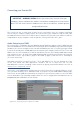
The Front Panel includes the input connectors for Mic, Line and Instrument signals, as well as the
input gain and monitoring controls.
1. Inputs 1 & 2 – “Combo” type input sockets - connect microphones, instruments (e.g., guitar),
or line level signals via XLR or ¼” (6.35 mm) jacks as appropriate.
2. GAIN 1 and GAIN 2 – adjust the input gain for input signals on inputs 1 and 2 respectively. The
gain controls have concentric bi-colour LED ‘rings’ to confirm signal level: green indicates
an input level of at least -24 dBFS (i.e., ‘signal present’), the ring then turns red when signal
level reaches 0 dBFS.
3. PAD – 10 dB pad for each input. Pressing this button reduces the sensitivity of the input; use
if feeding the input with a particularly high-level signal.
4. LINE/INST – Instrument/Line level switches for each input – switches gain to suit instrument
or line level signals.
5. 48V – phantom power switch for mic inputs - enables 48 V phantom power at XLR contacts of
both Combo connectors.
6. USB LED – illuminates when the unit receives USB bus power and is confirmed by the
computer as connected and operating correctly.
7. MIDI LED – illuminates when MIDI data is received at the MIDI IN port.
8. DIRECT MONITOR – rotary “blend” control letting you set your monitor mix as a balance of the
input signal(s) and the DAW playback.
9. STEREO/MONO – selects whether the inputs are summed to mono for monitoring.
10. MONITOR – main monitor output level control - sets the output level at the balanced (rear
panel) outputs of channels 1 and 2 at both the TRS and RCA (phono) connectors.
11. Headphone level – adjusts the output level at the front panel stereo headphone output.
12. Headphone SOURCE – allows you to select whether the headphones output is fed from Outputs
1 and 2 or Outputs 3 and 4 (as stereo pairs; modified by the setting of [9]).
13. Headphone socket – ¼” TRS output jack - connect your stereo headphones here.