MODEL#: FG7750PBE ITEM#: Generator OPERATOR’S MANUAL Warning: The Engine Exhaust from this product contains chemicals known to the State of California to cause cancer, birth defects or other reproductive harm. www.fordpower.
TABLE OF CONTENTS Introduction. ............................................................................................................................................................................3 Product Specifications. ................................................................................................................................................3 Parts Ordering / Customer Service. .....................................................................................................
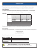
INTRODUCTION Thank you for purchasing this superior quality portable generator from Ford Power Equipment. When operating and maintaining this product as instructed in this manual, your generator will give you many years of reliable service. Product Specifications: This generator is an engine-driven, revolving field, alternating current (AC) portable generator.
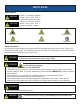
SAFETY RULES Safety Symbols WARNING! Indicates a potentially hazardous situation which could result in serious injury or death if not avoided. CAUTION! Indicates a potentially hazardous situation which could result in damage to equipment or property. Toxic Fumes Risk of electric shock Risk of fire Risk of explosion Hot surface Lifting hazard Safety Instructions The manufacturer cannot anticipate every possible hazardous circumstance that the user may encounter.
SAFETY RULES WARNING! Never exceed generator’s wattage / amperage capacity. This could damage the generator and / or connected electrical devices. • Check operating voltage and frequency requirements of all electrical devices prior to plugging them into the generator. • • Never start or stop engine with electrical devices plugged in to the receptacles. Failure to do so could damage the generator and / or connected electrical devices.
SAFETY RULES This generator produces a very high voltage which could result in burns or electrocution causing serious injury or death. Never handle the generator, electronic devices, or any cord while standing in water, while barefoot, or when hands or feet are wet. Always keep the generator dry. Never operate generator in rain or under wet conditions. Use a ground fault circuit interrupter (GFCI) in a damp or highly conductive area, such as metal decking or steel work.
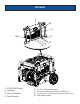
FEATURES A B C W D G F A - START/ON/OFF Switch B - Hour Meter C - Main Circuit Breaker D - Circuit Protectors EFGW- E Two 120 V GFCI duplex Receptacles. 120 Volt AC, 30 Amp twist lock receptacle (NEMA L5-30). 120 / 240 Volt AC, 30 Amp twist lock receptacle (NEMA L14-30).
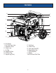
FEATURES H P I Q J K R L S M T U N V O H - Fuel Gauge I - Fuel Tank Vapor Vent J - Generator Frame K - Choke Lever L - Air Filter M - Handles & Grips N - Oil Drain Plug O - Support Leg (Foot) P - Fuel Tank Q - Fuel Fill Cap R - Fuel Valve (ON/OFF) S - Recoil Starter Grip T - Oil Fill (Dipstick) U - Battery V-No Flat Foam Filled Tires 8
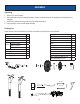
ASSEMBLY Unpacking 1. Place box on a level surface. 2. Remove all items from box except the generator. Make sure all items listed on the packing list are included and not damaged. 3. Cut down the sides of box being careful to avoid hitting the generator. 4. Leave generator on box to install wheel assembly. Packing List Check all loose parts to the following list. Contact your dealer if any loose parts are not included.
ASSEMBLY Remove Shipping Bracket (See fig 1) • Remove and discard the two RED shipping brackets and mounting hardware before starting the Generator. Attaching Wheels (See fig 2) • • • • • Parts needed - 2 wheels, 2 axles, 2 hair pins, 2 washers, 2 hub caps and 2 self-tapping screws. Raise or tilt generator so you can slide the wheel axle pin into the wheel, the washer, the wheel mounting hole located on the side of the frame.
ASSEMBLY Attaching Battery Cable (See fig 4) • • • • • • Parts needed - Black and Red battery cable The Red (+) Connector should be attached to the battery first. Remove the screw from the battery terminal. Place the screw through the eyelet and tighten the screw and make sure the terminal will not touch any part of the frame. Install the Red protection boot. Repeat these steps for the Black (-) Terminal. CAUTION! Be careful not to short across the terminals when installing.
ASSEMBLY ! DANGER/POISON NON-SPILLABLE SEALED BATTERY This is a ready filled, activated sealed battery. Never remove strip. Refer to owner’s manuall or instruction sheet for charging procedures. SHIELD EYES.
ASSEMBLY Adding Fuel (See fig 8) • • • Set generator on a clean and level surface in an area that is well ventilated. Remove fuel cap. Insert a funnel into the fuel tank and carefully pour gasoline into the tank until fuel level reaches 1 ½ inches below the top of the neck. Be careful not to overfill the tank to provide space for fuel expansion. CAUTION! You must add oil before first operating this generator. Always check oil level before each operation. DO NOT USE E15 OR E85 FUEL IN THIS UNIT.
OPERATION Grounding the Generator (See fig 9) The ground terminal located on the back of the generator frame must always be used to connect generator to a driven ground rod. Connect the ground terminal to the driven ground rod with a No 8 AWG (American Wire Gauge) copper wire. The wire connects to the terminal between the lock washer and nut. Tighten the nut securely to ensure proper connection.
OPERATION Never start or stop engine with electrical devices plugged in to the receptacles. Failure to do so could damage the generator and / or connected electrical devices. Always start the engine and let it stabilize before connecting any electronic devices. Disconnect all electronic devices before stopping the engine. WARNING! • • WARNING! • Pull cord recoils rapidly and pulls arm towards engine faster than you can let go which could result in injury.
OPERATION CAUTION! Do not connect 3-phase loads to generator. Extension Cord Selection Refer to the below table to ensure the extension cord used has the capacity to carry the required load. If the size of the cable is inadequate it can cause a voltage drop, which can damage the electrical device and cord. Current (Amps) 2.5 5 7.5 10 15 20 25 30 Load (Watts) 230V 600 1200 1800 2400 3800 4800 6000 7200 Maximum Cord Length #8 Wire #10 Wire X 1000 ft. X 500 ft. X 350 ft. X 250 ft. X 150 ft. 175 ft.
OPERATION Wattage Reference Guide (Wattages listed are just approximations.
OPERATION Hour Meter (See Fig 20) The digital hour meter operates whenever the engine is running and keeps track of how many hours the unit has been used. Use this meter along with the manual to determine when and what type of service on the unit is needed. The display will show the word “LUBE” at the first 25 hours of operation and again at every 100 hours of operation after. Fig 20 Power Management • • • Start engine without anything connected to generator.
MAINTENANCE Creating a Temporary Cold Weather Shelter In an emergency, the original shipping carton can be used as a temporary shelter. The shelter should hold enough heat created by the generator to prevent icing. 1. Cut off all flaps. 2. Cut off one of the long sides of the carton to expose the units muffler and exhaust. Do not enclose the muffler / exhaust side of the generator. 3. Slide carton over generator. If necessary, remove the wheel assembly for fit. 4.
MAINTENANCE Changing Oil (See Fig 21) • • • • • • • • Run the Generator until the Engine is warm. Place generator on a level surface. Remove the crankcase dipstick. Place an oil pan underneath the oil drainage bolt to collect used oil. Remove the oil drainage plug and allow oil to drain completely. Reinstall oil drainage plug, tighten securely. Carefully add SAE 10W-30 to empty reservoir until the oil reaches the outer edge of the oil fill hole (Crankcase Dipstick hole). Replace crankcase dipstick.
MAINTENANCE CAUTION! Used oil should be disposed of at an approved disposal site. See your local oil retailer for more information. Air Filter (See Fig 22) A dirty air filter will reduce the life span of the engine, make it difficult to start the engine, and reduce the unit’s performance. • To clean, remove the air filter cover. • Carefully pull the air filter out by lifting up along the edges. • Remove dirt from filter by tapping on it or having it blown out. Replace with new filter annually.
MAINTENANCE Carburetor Adjustment The carburetor is low emission and is equipped with a non-adjustable idle mixture valve. If adjustment is needed contact an authorized dealer. Replacing Fuel Filter (See Fig 25) Occasionally the fuel filter may become clogged and need replacing. To purchase a replacement fuel filter contact PULSAR customer service or your local small Engine repair shop. • Turn the fuel valve to the “OFF” position.
MAINTENANCE Draining the carburetor • Turn the engine OFF. • Turn the fuel valve to the OFF position. • Position a suitable container under the carburetor drain screw to catch fuel; loosen the screw. • Allow fuel to drain completely into container. • Retighten drain screw. CAUTION! Consult your local hazardous waste management in your area for the proper way to dispose of used fuel.
TROUBLESHOOTING Problem Engine is running, but AC output is not available Cause 1. Open circuit breaker 2. Poor connection 3. Defective cord set 4. Connected device is faulty 5. Fault in generator Engine runs well without load but bogs 1. Short circuit in connected device down when loads are connected 2. Generator is overloaded 3. Clogged fuel filter 4. Engine speed is too slow 5. Short circuit in generator Engine will not start, shuts down during 1.
DIAGRAMS 25
WARRANTY Ford Power Equipment Limited 2 Year Warranty: From the date of original purchase, Ford Power Equipment warrants to the original purchaser that each portable generator sold, shall be free from defect in material and workmanship for the items and time period set forth below.
WARRANTY What this Warranty Does Not Cover: • Normal wear: This warranty excludes normal wear items such as filters, spark plugs, gaskets, O-rings, adapter cord sets, wheels, and starting batteries. • Maintenance: This warranty does not apply to tune-ups or routine maintenance and does not cover any adjustments or repairs not performed by an authorized repair facility.