JODY-W263 Host-based multiradio module with Wi-Fi and Bluetooth 5 Integration Instructions Abstract This document describes the system integration of JODY-W263 module into a host product. This host-based modules support Wi-Fi 802.11n/ac and Bluetooth® 5 and is designed for both simultaneous and independent operations. The JODY-W263 module includes an integrated MAC/baseband processor and RF front-end components.
Document Information Title Subtitle Document type Document name Revision and date Disclosure restriction JODY-W2 Host-based multiradio modules with Wi-Fi and Bluetooth 5 Integration Instructions FSS JODY-W263 System integration manual Rev 02 08-Sep-2022 Confidential This document applies to the following products. Product name JODY-W263-00B Document Information FSS JODY-W263 Integration Instructions Rev 02.docx www.foresightsports.
Table of Contents 1 List of applicable FCC rules ............................................................................................................... 5 2 Summary of operational use conditions ......................................................................................... 5 3 4 5 6 2.1 Antenna configuration ............................................................................................................... 5 2.2 Antenna gain .........................................
8 7.1.3 Canada (ISED) .................................................................................................................... 25 7.1.4 ISED compliance statement............................................................................................. 26 Product Testing ................................................................................................................................. 28 8.1 u-blox in-line production testing .................................................
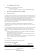
1 List of applicable FCC rules The following FCC rules are applicable to the equipment: • • CFR 47, Part 15, Subpart C CFR 47, Part 2, Subpart J – Radiofrequency radiation exposure: portable devices 2 Summary of operational use conditions 2.1 Antenna configuration In addition to the general requirement to use only authorized antennas, the grant also requires a separation distance of at least 20 cm from the antenna(s) to all persons.
2 – 10 OFDM 20 MHz 6, 9, 12, 18, 24, 36, 48, 54 Mbps 11 OFDM 20 MHz 6, 9, 12, 18, 24, 36, 48, 54 Mbps 1 OFDM 20 MHz HT20 MCS0-MCS7 2 – 10 OFDM 20 MHz HT20 MCS0-MCS7 11 OFDM 20 MHz HT20 MCS0-MCS7 3 OFDM 40 MHz HT40 MCS0-MCS7 4–8 OFDM 40 MHz HT40 MCS0-MCS7 9 OFDM 40 MHz HT40 MCS0-MCS7 Table 1: Wi-Fi power table for operation in the 2.
3 RF Exposure conditions 3.1 Installation Instructions The module is approved for use in a mobile RF exposure environment. A minimum separation distance of 20 cm must be maintained between the antenna and nearby persons. The module is not approved for co-location with any other modules. 3.2 Warning A warning must be placed in the host product user instructions stating that: 1) “This device is approved for use in a mobile rf exposure environment.
For information describing how to properly design circuits compliant with these requirements, see Antenna interfaces. 4.2 Approved antenna designs JODY-W2 modules come with a pre-certified design that can be used to save costs and time during the certification process. To minimize this effort, the customer is required to implement antenna layout according to u-blox antenna reference designs. Reference design source files can be provided on request by u-blox.
4.3 Other remarks 4.3.1 Unused pins ☞ JODY-W2 modules have pins that are reserved for future use (NC). These pins must be left unconnected on the application board. 4.3.2 GPIO usage ☞ The reconfiguration of signals marked as GPIOs on the JODY-W2 module for applications not listed in this document depends on the respective firmware release. 5 Design-in 5.
Accurate design is required to ensure proper functionality. Follow the General highspeed layout guidelines and recommendations for the High-speed UART interface. 5.2 Antenna Interfaces JODY-W2 modules provide the following two RF interfaces for connecting the external antennas: • • The ANT0 port for Bluetooth connectivity. The ANT1 port for Wi-Fi connectivity.
Figure 1: Transmission line trace design To properly design a 50 Ω transmission line, the following remarks should be considered: • • • The designer should provide enough clearance from surrounding traces and ground in the same layer; in general, a trace to ground clearance of at least two times the trace width should be considered, and the transmission line should be “guarded” by ground plane area on each side.
• • • • • • For PCBs using components larger than 0402 and dielectric thickness below 200 µm, it is recommended to add a keep-out (that is, clearance, a void area) on the ground reference layer below any pin present on the RF transmission lines to reduce parasitic capacitance to ground. The transmission lines width and spacing to GND must be uniform and routed as smoothly as possible: route RF lines in 45° angle. Add GND stitching vias around transmission lines as shown in Figure 2.
5.2.2 Antenna Design Designers must take care of the antennas from all perspective at the very start of the design phase when the physical dimensions of the application board are under analysis/decision, since the RF compliance of the device integrating JODY-W2 module with all the applicable required certification schemes heavily depends on antennas radiating performance.
A numerical example for estimating the physical restrictions on a PCB is given here: Frequency = 2.4 GHz → Wavelength = 12.5 cm → Quarter wavelength = 3.5 cm o Radiation performance depends on the whole product and antenna system design, including product mechanical design and usage. Antennas should be selected with optimal radiating performance in the operating bands according to the mechanical specifications of the PCB and the whole product.
Item Isolation (in-band) Requirements S21 > 30 dB recommended Isolation (out-of-band) S21 > 35 dB recommended S21 > 30 dB acceptable Remarks The antenna-to-antenna isolation is the S21 parameter between the two antennas in the band of operation. Lower isolation might be acceptable depending on use-case scenario and performance requirements.
Manufacturer Hirose Series U.FL® Ultra Small Surface Mount Coaxial Connector I-PEX MHF® Micro Coaxial Connector Tyco UMCC® Ultra-Miniature Coax Connector Amphenol RF AMC® Amphenol Micro Coaxial Lighthorse Technologies, Inc. IPX ultra micro-miniature RF connector Table 9: U.FL compatible plug connector Remarks Recommended Typically, the RF plug is available as a cable assembly. Different types of cable assembly are available; the user should select the cable assembly best suited to the application.
5.2.2.2 Integrated Antenna Design If integrated antennas are used, the transmission line is terminated by the antennas themselves. Follow the guidelines mentioned below: • • • • • • The antenna design process should start together with the mechanical design of the product. PCB mock-ups are useful in estimating overall efficiency and radiation path of the intended design during early development stages. Use antennas designed by an antenna manufacturer providing the best possible return loss (or VSWR).
This document supports a connector-based design for the use of external antennas (one for each antenna pin of the module). 6.2 General description and requirements JODY-W2 series modules provide two RF interfaces for connecting external antennas. The antenna ports ANT0 and ANT1 have a nominal characteristic impedance of 50 Ω and must be connected to the related antenna through a 50 Ω transmission line to allow proper impedance matching along the RF path.
Item Isolation (in-band) Remarks The antenna to antenna isolation is the S21 parameter between the two antennas in the band of operation. Isolation S21 > 35 dB recommended Out-of-band isolation is evaluated (out-of-band) S21 > 30 dB acceptable in the band of the aggressor to ensure that the transmitting signal from the other radio is sufficiently attenuated by the receiving antenna to avoid saturation and intermodulation effect at the receiver’s port. Envelope correlation ECC < 0.
Figure 4: Test set-up 3.1 RF trace PCB routing The PCB routing connecting the module’s antenna pins to module board U.FL connectors are designed with coplanar microstrips. Coplanar microstrips are also used on the carrier board connecting the U.FL connectors with the SMA connectors to which the external antennas or test equipment are connected. Figure 5 and Table 12 shows the design stack-up including dimensions of the 50 Ω coplanar microstrips implemented.
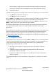
Figure 5: Coplanar micro-strip dimension specification Item Value S 200 µm W 700 µm T 35 µm H 800 µm 𝜀r 4.3 Table 12: Coplanar micro-strip specification The mechanical dimensions of the module board’s microstrips and position of the pi network impedance matching components are shown in Figure 6. Figure 7 shows the components used for the PI network impedance matching. Here only series 0 ohm resistors are used. The inner layers have the same dimensions and are filled with ground.
Figure 7: Component selection for RF matching network on module board using 0 ohm series resistor The carrier board RF traces includes pi network matching components and are routed as coplanar microstrips. Here 10 pF capacitors in series are implemented. Figure 8: Carrier board Antenna micro strip implementation Document Information FSS JODY-W263 Integration Instructions Rev 02.docx www.foresightsports.
Figure 9: Component selection for RF matching network on carrier board using 10 pF series capacitors. Document Information FSS JODY-W263 Integration Instructions Rev 02.docx www.foresightsports.
6.4 Parts Part Description Evaluation board (EVB) Evaluation board for JODY-W263 series modules. The board includes SMA antenna connectors that connect to external antennas for Wi-Fi and Bluetooth. It has two internal dual-band WiFi/Bluetooth antennas. Internal Antennas (2) 2 x dual band Wi-Fi/Bluetooth antenna, Pulse W3006 Coax RF cable U.FL-2LP(V)-04N1-A-(40) Outline 7 Label and Compliance Information 7.1 Label requirements 7.1.
7.1.2 FCC Compliance statement JODY-W263 module has modular approval and complies with Part 15 of the FCC Rules. Operation is subject to the following two conditions: 1. This device may not cause harmful interference, and 2. This device must accept any interference received, including interference that may cause undesired operation.
Model JODY-W263-00B ISED certification number 28505-JODYW263FSS 7.1.4 ISED compliance statement JODY-W263-00B module complies with ISED (Innovation, Science and Economic Development Canada) license-exempt RSSs. Operation is subject to the following two conditions: 1. This device may not cause interference, and 2. This device must accept any interference, including interference that may cause undesired operation of the device.
Cet équipement est conforme aux limites d'exposition de rayonnement d'ISED RSS-102 déterminées pour un environnement non contrôlé. Cet équipement devrait être installé et actionné avec la distance minimum 20 cm entre le radiateur et votre corps. Cet émetteur radio, IC: 8595A-JODYW263 été approuvé par ISED pour fonctionner avec les types d’antenne énumérés ci-dessous avec le gain maximum autorisé et l’impédance nécessaire pour chaque type d’antenne indiqué.
8 Product Testing 8.1 u-blox in-line production testing As part of our focus on high quality products, u-blox maintain stringent quality controls throughout the production process. This means that all units in our manufacturing facilities are fully tested and that any identified defects are carefully analyzed to improve future production quality.
be necessary to confirm RF performance. Testing over analog and digital interfaces is also unnecessary during an OEM production test.
9 Information on test modes and additional test For end host implementation the user must refer to the manufacturer integration manual to implement software/firmware that can be used to manipulate the module configuration and put it into to special test modes, set and verify regional power limits and any debugging required.
Revisions Revision Description Date Author 01 Initial Release Changed section 4 from Approved antennas to Antenna interfaces, Added section 5 Design-in, Added section 6 Antenna reference design, added section 8 Production testing, Label and compliance information is now section 7, Information on test modes and additional test is now section 9, additional test requirements is now section 10. 19 May 2022 P. Hicks 08 Sep 2022 P.