
Integration Instructions


Document Information Page 10 of 31
FSS JODY-W263 Integration Instructions Rev 02.docx
www.foresightsports.com
Accurate design is required to ensure proper functionality. Follow the General high-
speed layout guidelines and recommendations for the High-speed UART interface.
5.2 Antenna Interfaces
JODY-W2 modules provide the following two RF interfaces for connecting the external antennas:
• The ANT0 port for Bluetooth connectivity.
• The ANT1 port for Wi-Fi connectivity.
Both the ANT0 and the ANT1 ports have a nominal characteristic impedance of 50 Ω and must
be connected to the related antenna through a 50 Ω transmission line to allow proper
impedance matching along the RF path. A bad termination of the ANT0 pin (Bluetooth) or the
ANT1 pin (Wi-Fi) may result in poor performance of the module.
For the dual antenna modules, the isolation between the two antennas should be maximized,
the requirements specified in Table 7 and Table 8 should be followed to ensure good
performance.
⚠ According to FCC regulations, the transmission line from the antenna pin in the module to the
antenna or antenna connector on the host PCB is considered part of the approved antenna
design. Consequently, module integrators must either follow exactly one of the antenna
reference designs used in the module’s FCC type approval or certify their own designs. See also
the antenna reference design.
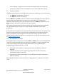
5.2.1 RF Transmission Line Design
RF transmission lines such as the ones from the ANT0 and ANT1 pins up to the related antenna
connectors must be designed so that the characteristic impedance is as close as possible to 50
Ω illustrates the design options and the main parameters to be considered when
implementing a transmission line on a PCB:
• Microstrip: track coupled to a single ground plane, separated by dielectric
material),
• Coplanar microstrip: track coupled to ground plane and side conductors,
separated by dielectric material).
• Stripline: track sandwiched between two parallel ground planes, separated by
dielectric material).
The coplanar microstrip is the most common configuration for a printed circuit board
(PCB).