40 MULTI-PROCESS WELDER OPERATING MANUAL ENGLISH INCLUDES: Welding Machine, 20 Amp –15 Amp Plug Adapter, MIG Gun, Extra 0.030” Contact Tip, Stick Electrode Holder, and Ground Cable and Clamp CAT# 271 REV 12.19.17 1 WWW.FORNEYIND.
FIVE WAYS TO ORDER Web: www.forneyind.com Phone: 800-521-6038 Fax: 970-498-9505 Mail: Forney Industries 2057 Vermont Drive Fort Collins, CO 80525 Email: sales@forneyind.com U.S. Facilities: - Fort Collins, CO - Tipp City, OH Forney Promise We are committed to your success regardless of location, size or needs. We understand it is your goal to get the job done right, and we are ready to help you do just that.
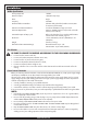
STOP! PLEASE DO NOT RETURN TO THE STORE If you have questions or problems with your new welder, please contact customer service at 1-800-521-6038 Monday through Friday from 7 a.m. - 5 p.m. (MST) or www.forneyind.com/about-us/contact-us. Please take time to register your product at www.forneyind.com/support/product-registration. Thank you and enjoy your new welder. For the most up-to-date warranty information, visit www.forneyind.com WWW.FORNEYIND.
Box Contents Table of Contents WARRANTY................................................................................................................................................................. 3 TABLE OF CONTENTS................................................................................................................................................... 4 SYMBOLS LEGEND................................................................................................................................
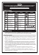
CAUTION! BEFORE INSTALLING, OPERATING OR CARRYING OUT MAINTENANCE ON THE MACHINE, READ THE CONTENTS OF THIS MANUAL CAREFULLY, PAYING PARTICULAR ATTENTION TO THE SAFETY RULES AND HAZARDS.
• CSA W117.2 - Code for SAFETY IN WELDING AND CUTTING. - Obtainable from Canadian Standards Association, 178 Rexdale Blvd., Etobicoke, Ontario M9W 1R3 - www.csa.ca • ANSI Z87.1 - SAFE PRACTICE FOR OCCUPATION AND EDUCATIONAL EYE AND FACE PROTECTION Obtainable from the American National Standards Institute, 11 West 42nd St., New York, NY 10036 Telephone (212) 642A900, Fax (212) 398-0023 - www.ansi.
background exists in your welding area, either remove it or cover it with something non-flammable and nonreflective. Reflective arc rays can also cause skin burn in addition to eye injury. • Flying sparks can injure. Wear proper safety equipment to protect eyes and face. Shape tungsten electrode on grinder wearing proper protection and in a safe location. Keep flammables away and prevent fire from flying sparks.
• If a cylinder is not in use or connected for use, keep a valve protection cap in place to protect the valve. • Keep cylinders upright and securely chain them to a fixed support to prevent tipping. • Keep cylinders away from areas where they may be subjected to physical damage or accidentally struck. Keep them a safe distance from any source of flame, sparks, or heat. • Do not weld or cut in an area where the air may contain flammable dust (such as grain dust), gas, or liquid vapors (such as gasoline).
• Do not attempt to weld if any part of clothing or body is wet. • Do not allow the welding equipment to come in contact with water or moisture. • Do not drag welding cables, MIG gun, or welder INPUT POWER CABLE (12) through or allow them to come into contact with water or moisture. • Do not touch welder, attempt to turn welder ON or OFF if any part of the body or clothing is moist or if you are in physical contact with water or moisture.
Installation Welder Specifications Primary (input) volts 120VAC Maximum Output 140A (DC output only) Phase Single Frequency 50/60Hz Recommended Circuit Breaker 20A time-delay (slow-blow) breaker minimum (30A for maximum performance) Extension Cord Recommendations 3 conductor #12AWG or larger up to 25 ft.
Using the 20 Amp – 15 Amp Plug Adapter If a 20A outlet (with 30A circuit breaker) is not available, you can connect your 140 MP Forney Easy Weld™ welder to 15A outlet (with a 20A breaker) using the plug adapter. When using the plug adapter, use lower power settings on the machine to avoid frequent circuit breaker trips. At maximum settings, the machine will draw more than 20 amps regularly.
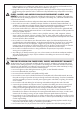
Getting to Know Your Multi-Process Welder Description Your new single phase inverter multi-process welder offers three welding processes in the same power source. These processes can be selected with the process SELECTOR SWITCH (1) on the front panel of the unit. Flux-Cored Wire Welding, “FCAW” and MIG Welding, “GMAW” The operator is required to set both the wire speed (RIGHT KNOB) (5) and the welding voltage (LEFT KNOB) (4). Stick Welding, “SMAW” Both rutile and basic electrodes can be welded.
1 2 3 4 5 6 7 8 9 13 14 10 11 12 WWW.FORNEYIND.
Installing the MIG Gun Assembly • Attach the standard MIG welding gun to the threaded connection on the front of the welder. Gas Cylinder and Regulator Connection The gas cylinder (not supplied) should be located near the rear of the welder, in a well-ventilated area and securely fixed to the work bench or to the wall to ensure that it will not fall. For safety and economy, ensure that the regulator is fully closed (turned counter-clockwise) when not welding and when fitting or removing the gas cylinder.
INSTALLING 4-INCH SPOOL (SEE FIGURE FOR PART IDENTIFICATION): 1. 2. 3. 4. 5. Open the access panel. Unscrew and remove the wire spool retention cap used for 8-inch spools (A) and store it someplace safe. Remove the spindle adapter for 8-inch spools (B) and store it someplace safe. Remove the nut (C), spring (D), and washers (E).
12. Cut off the excess wire that extends past the end of the nozzle. 13. Fine tune the wire drive pressure with the pressure arm adjustment knob (G). a. Turn the wire drive pressure adjustment knob clockwise, increasing the drive pressure until the wire seems to feed smoothly without slipping. NOTE: If TOO MUCH pressure is applied you can crush the wire and create wire feeding problems. If TOO LITTLE pressure is applied, the wire will slip on the drive rolls and wire will not feed. b.
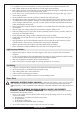
140 MP SER #: CSA-C22.2 NO 60-M1990 UL551 (8 Ed.) min #A/min #V – max #A/max #V Uo=##.#V X Y% Z% 100% I2 ##A ##A ##A U2 ##.#V ##.#V ##.#V U1=120V I1max =##.#A I1eff =##.#A min #A/min #V – max #A/max #V Uo=##.#V X Y% Z% 100% I2 ##A ##A ##A U2 ##.#V ##.#V ##.#V U1=120V I1max =##.#A I1eff =##.#A min #A/min #V – max #A/max #V Uo=##.#V X Y% Z% 100% I2 ##A ##A ##A U2 ##.#V ##.#V ##.#V U1=120V I1max =##.#A I1eff =##.
• Attach the ground clamp to the bare metal to be welded, making sure of good contact. • Make sure that the wire-roller groove in the roller corresponds to the diameter and type of wire being used. • Plug the machine into a suitable outlet. • Completely open the gas cylinder valve. Adjust the gas pressure regulator to the correct flow rate. (Not applicable to Stick “SMAW” process.) EXPOSURE TO A WELDING ARC IS EXTREMELY HARMFUL TO THE EYES AND SKIN.
Gas Selection Select the appropriate shielding gas in accordance to material being welded and wire being used. The table below can give you some useful indications: METAL GAS NOTE Mild Steel CO2 Argon + CO2 Argon + CO2 + Oxygen Argon controls spatter Oxygen improves arc stability Stainless Steel Argon + CO2 + Oxygen Argon + Oxygen Arc stability. Minimum splatter Copper, Nickel & Alloys Argon Suitable for light gauges because of low flowability of the weld pool.
Setup for Stick Welding (SMAW) • Switch the Process SELECTOR SWITCH (1) on the front panel to the middle position. • Remove the MIG ELECTRODE POLARITY JUMPER (9) from the POSITIVE (+) and NEGATIVE (-) DINSE SOCKETS (8 and 7). • Check the electrode packaging to determine the recommended polarity and connect the electrode holder and ground clamp to the POSITIVE (+) and NEGATIVE (-) DINSE SOCKETS (8 and 7) accordingly.
140 MP TIG SET-UP CHART MATERIAL THICKNESS MATERIAL (Wire) GAS TUNGSTEN ELECTRODE ø Regulation Knob Mild Steel 100% Argon 1/16” (1.6 mm) 22 Gauge .030” (.8 mm) 16 Gauge 1/16” (1.6 mm) 1/8” (3 mm) 3/16” (5 mm) Left Knob Left Knob Left Knob Left Knob 1-3 4-6 6-8 8-10 CANNOT WELD ALUMINUM Welding Tips: • Always weld clean, dry and well-prepared material. • Hold gun at a 45° angle to the workpiece with nozzle about 1/2” from the surface. • Move the gun smoothly and steadily as you weld.
Maintenance & Servicing General Maintenance This welder has been engineered to need minimal service providing that a few very simple steps are taken to properly maintain it. 1. Keep the cabinet cover closed at all times unless the wire needs to be changed or the drive pressure needs adjusting. 2. Keep all consumables (contact tips, nozzles, and liner) clean and replace when necessary. See “Consumable Maintenance” (below) and “Troubleshooting” (page 22) for detailed information. 3.
Troubleshooting The following is a troubleshooting table provided to help you determine a possible remedy when you are having a problem with your welder. This table does not provide all possible solutions, only those possibilities considered likely to be common faults. PROBLEM POSSIBLE CAUSE POSSIBLE SOLUTION Bad ground or loose ground connection. Check connection of the ground cable to the ground clamp. Tighten cable connection to ground clamp if needed.
PROBLEM POSSIBLE CAUSE POSSIBLE SOLUTION Weld parameters too low. Adjust welding parameters Too long or improper extension cord. Use a proper extension cord (#12 AWG wire or heavier, no longer than 25 ft.). See “Extension Cords”, page 11. Wrong type or size wire. Use 0.023” (0.6mm) - 0.030” (0.8mm) wire. See “Welding Wire Selection” (page 18). Use ER70S-6 or E71T-GS selfshielding flux-core wire. Poor ground connection or gun connection. Reposition clamp and check cable to clamp connection.
POSSIBLE CAUSE POSSIBLE SOLUTION Machine is drawing too much amperage due to use of larger size wire. Use the smallest wire possible for this welder. 0.030-inch wire is strongly recommended. Machine is not the only piece of electrical equipment on the circuit. Make sure the welder is on a dedicated circuit or is the only thing plugged on a circuit. Circuit breaker is incorrect/insufficient for use with this machine.
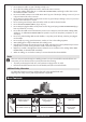
Machine Parts Diagram & Replacement Parts List NO. PART NUMBER ITEM DESCRIPTION 1 85500 MIG Gun 2 85667 Ground (25 Dinse) 3 85669 Electrode Holder (25 Dinse) 4 - Plug Adapter (20A – 15A) 1 2 3 4 26 WWW.FORNEYIND.
MIG Gun Consumables List NO. 1 PART NUMBER ITEM DESCRIPTION 60170 Tip (Tweco® 11-24) 60171 Tip (Tweco® 11-30) 60172 Tip (Tweco® 11-35) 60173 Tip (Tweco® 11-45) NO. 2 3 4 PART NUMBER ITEM DESCRIPTION 85339 Diffuser (Tweco® 35-50) 85336 Nozzle (Tweco® 21-50) 85337 Nozzle (Tweco® 21-62) 100202 Liner 2 4 1 3 TIG Torch & TIG Consumables List (SOLD SEPARATELY) NO.
User Notes _______________________________________________________________________________________________ ________________________________________________________________________________ ________________________________________________________________________________ ________________________________________________________________________________ ________________________________________________________________________________ ________________________________________________________________________________
User Notes _______________________________________________________________________________________________ ________________________________________________________________________________ ________________________________________________________________________________ ________________________________________________________________________________ ________________________________________________________________________________ ________________________________________________________________________________
User Notes _______________________________________________________________________________________________ ________________________________________________________________________________ ________________________________________________________________________________ ________________________________________________________________________________ ________________________________________________________________________________ ________________________________________________________________________________
User Notes _______________________________________________________________________________________________ ________________________________________________________________________________ ________________________________________________________________________________ ________________________________________________________________________________ ________________________________________________________________________________ ________________________________________________________________________________
Forney Industries, Inc. 2057 Vermont Drive Fort Collins, CO 80525 800-521-6038 www.forneyind.