80 ST STICK/TIG ARC WELDER OPERATING MANUAL ENGLISH INCLUDES: Welding Machine, Stick Electrode Holder and Ground Cable and Clamp CAT# 291 REV 10.22.18 1 WWW.FORNEYIND.
FIVE WAYS TO ORDER Web: www.forneyind.com Phone: 800-521-6038 Fax: 970-498-9505 Mail: Forney Industries 2057 Vermont Drive Fort Collins, CO 80525 Email: sales@forneyind.com U.S. Facilities: - Fort Collins, CO - Tipp City, OH Forney Promise We are committed to your success regardless of location, size or needs. We understand it is your goal to get the job done right, and we are ready to help you do just that.
STOP! PLEASE DO NOT RETURN TO THE STORE If you have questions or problems with your new welder, please contact customer service at 1-800-521-6038 Monday through Friday from 7 a.m. - 5 p.m. (MST) or www.forneyind.com/about-us/contact-us. Please take time to register your product at www.forneyind.com/support/product-registration. Thank you and enjoy your new welder. For the most up-to-date warranty information, visit www.forneyind.com WWW.FORNEYIND.
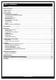
Box Contents Table of Contents WARRANTY................................................................................................................................................................. 3 TABLE OF CONTENTS................................................................................................................................................... 4 SYMBOLS LEGEND................................................................................................................................
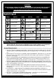
CAUTION! BEFORE INSTALLING, OPERATING OR CARRYING OUT MAINTENANCE ON THE MACHINE, READ THE CONTENTS OF THIS MANUAL CAREFULLY, PAYING PARTICULAR ATTENTION TO THE SAFETY RULES AND HAZARDS.
• ANSI Z87.1 - SAFE PRACTICE FOR OCCUPATION AND EDUCATIONAL EYE AND FACE PROTECTION Obtainable from the American National Standards Institute, 11 West 42nd St., New York, NY 10036 Telephone (212) 642A900, Fax (212) 398-0023 - www.ansi.org • NFPA 51B: STANDARD FOR FIRE PREVENTION DURING WELDING, CUTTING, AND OTHER HOT WORKObtainable from the National Fire Protection Association, 1 Batterymarch Park, P.O. Box 9101, Quincy, MA 02269-9101 Telephone (617) 770-3000 Fax (617) 770-0700 - www.nfpa.
• Flying sparks can injure. Wear proper safety equipment to protect eyes and face. Shape tungsten electrode on grinder wearing proper protection and in a safe location. Keep flammables away and prevent fire from flying sparks. FUMES, GASSES, AND VAPORS CAN CAUSE DISCOMFORT, ILLNESS, AND DEATH! To reduce the risk, read, understand, and follow the safety instructions.
• Keep cylinders away from areas where they may be subjected to physical damage or accidentally struck. Keep them a safe distance from any source of flame, sparks, or heat. • Do not weld or cut in an area where the air may contain flammable dust (such as grain dust), gas, or liquid vapors (such as gasoline). • Do not handle hot metal, such as the workpiece or electrode stubs, with bare hands. • Wear leather gloves, heavy long sleeve shirt, cuff-less pants, high-topped shoes, helmet, and cap.
• Do not drag welding cables, TIG torch, electrode holder or welder INPUT POWER CABLE (8) through or allow them to come into contact with water or moisture. • Do not touch welder, attempt to turn welder ON or OFF if any part of the body or clothing is moist or if you are in physical contact with water or moisture. • Do not attempt to plug the welder into the power source if any part of body or clothing is moist, or if you are in physical contact with water or moisture.
Installation Welder Specifications Primary (input) volts 120VAC/230VAC Maximum Output 120V - 100A (DC output only) 230V - 180A (DC output only) Phase Single Frequency 50/60Hz Recommended Circuit Breaker 120V - 10A time-delay (slow-blow) breaker minimum (30A for maximum performance) 230V - 30A time-delay (slow-blow) breaker minimum (50A for maximum performance) Extension Cord Recommendations 3 conductor #12AWG or larger up to 25 ft.
Generators This welder can be operated from an AC generator. Ensure that the generator can supply a minimum of 4,000 watts for (120V operation) and (8,000 watts for 230V) of continuous output. The generator must not have an autoidle fuel saving feature or must have the option to turn auto-idle off. The generator must run at full speed at all times while your welder is plugged into it or you risk damaging your welder.
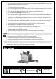
Getting to Know Your Welder Description Your new single phase inverter welder offers Stick and TIG welding processes in the same power source. These processes can be selected with the process SELECTOR SWITCH (1) on the front panel of the unit. Stick Welding, “SMAW” Both rutile and basic electrodes can be welded. Welding current is adjusted using the AMPERAGE ADJUSTMENT KNOB (4). TIG Welding, “GTAW” In the TIG position, a TIG torch with a gas valve in the handle is required.
1 2 3 4 5 — 6 + 7 8 WWW.FORNEYIND.
Operation Performance Data Plate and Duty Cycle On the machine, there is a plate that includes all the operating specifications for your new unit. The serial number of the product is also found on this plate. The duty cycle rating of a welder defines how long the operator can weld and how long the welder must rest and be cooled. Duty cycle is expressed as a percentage of 10 minutes and represents the maximum welding time allowed. The balance of the 10-minute cycle is required for cooling.
Welding Preparation An important factor in making a satisfactory weld is preparation. This includes studying the process and equipment and practicing welding before attempting to weld finished product. An organized, safe, ergonomic, comfortable, and well-lit work area should be prepared for the operator. The work area should specifically be free of all flammables with both a fire extinguisher and a bucket of sand available.
Setup for TIG Welding (GTAW) with Lift Arc Setting up the Equipment for TIG Welding (GTAW): Lanthanated Tungsten 1/16” to 1/8” (MAX) recommended for use. WARNING: TIG TORCH IS ALWAYS LIVE (ELECTRICALLY HOT). Use caution and ensure the TIG torch is not in contact with or near conductive or grounded materials. • • • Switch the Process SELECTOR SWITCH (1) on the front panel to the right position. Connect the TIG torch cable to the NEGATIVE (-) DINSE SOCKET (5) of the welder.
Maintenance & Servicing General Maintenance This welder has been engineered to need minimal service providing that a few very simple steps are taken to properly maintain it. 1. Replace INPUT POWER CABLE (8), ground cable, ground clamp, or torch/electrode cable when damaged or worn. 2. Avoid directing grinding particles towards the welder. These conductive particles can build up inside the machine and cause severe damage. 3. Periodically clean dust, dirt, grease, etc. from your welder.
PROBLEM Low output or non-penetrating weld. POSSIBLE CAUSE POSSIBLE SOLUTION Weld parameters too low. Adjust welding parameters Too long or improper extension cord. Use a proper extension cord (#12 AWG wire for 120V or #8 AWG for 230V or heavier, no longer than 25 ft.). See “Extension Cords”, page 11. Poor ground connection or torch/electrode Reposition clamp and check cable to connection. clamp connection. Check connection of ground cable, torch or electrode holder Input power too low.
Machine Parts Diagram & Replacement Parts List NO. PART NUMBER ITEM DESCRIPTION 1 85667 Ground (25 Dinse) 2 85669 Electrode Holder (25 Dinse) 2 1 WWW.FORNEYIND.
TIG Torch & TIG Consumables List (SOLD SEPARATELY) NO. 20 PART NUMBER ITEM DESCRIPTION 1 85657 Tig Torch (9FV) 2 85454 Cup (10N48) 3 85455 Collet (10N23 (1/16in)) 4 85459 Collet Body (10N31 (1/16in)) 5 85465 Back Cap (57Y02 (4in)) 6 85450 Electrode (1/16” x 7”) WWW.FORNEYIND.
User Notes _______________________________________________________________________________________________ ________________________________________________________________________________ ________________________________________________________________________________ ________________________________________________________________________________ ________________________________________________________________________________ ________________________________________________________________________________
Forney Industries, Inc. 2057 Vermont Drive Fort Collins, CO 80525 800-521-6038 www.forneyind.