
Network Device Quick Start Guide


© Copyright 2008 Fortinet Incorporated. All rights reserved.
Products mentioned in this document are trademarks or registered trademarks
of their respective holders.
Regulatory Compliance
FCC Class B Part 15 CSA/CUS
14 October 2008
Visit these links for more information and documentation for your Fortinet product.
Technical Documentation - • http://docs.forticare.com
Fortinet Knowledge Center - • http://kc.forticare.com
Fortinet Technical Support - • http://support.fortinet.com
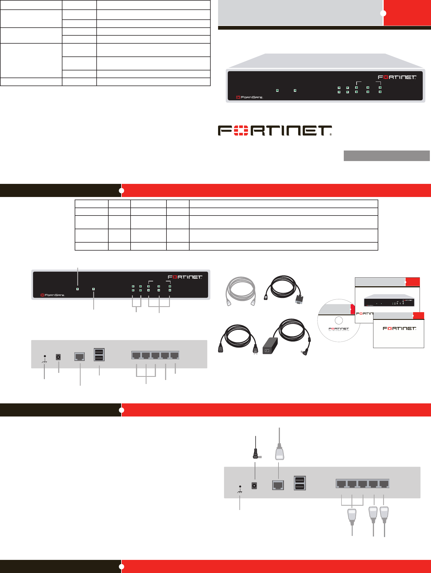
Connecting
WAN1 WAN2
POWER STATUS
INTERNAL
321
LINK / ACT
10/100
50B-LENC
123
USB
WAN2 WAN1
DC+12V
WAN1 WAN2
POWER STATUS
INTERNAL
321
LINK / ACT
10/100
Power
Connection
RJ-45 Serial
Connection
USB
WAN2
WAN1
Power LED
Status LED
Internal Interface,
switch connectors
1,2,3
WAN 1,2
Interface
Internal
Interface
Back
Front
Ground
50B-LENC
Straight-through
Ethernet cable
Power Cable
RJ-45 to
DB-9 Serial Cable
FortiGate-30B
Tools and Documenation
Copyright 2008 Fortinet Incorporated. All rights reserved.
Trademarks
Products mentioned in this document are trademarks.
QuickStart Guide
Welcome | Bienvenue | Willkommen | 歓迎 | Bienvenido | Benvenuto
WAN1 WAN2
POWER STATUS
INTERNAL
321
50B-LENC
Power Supply
123
USB
WAN2 WAN1
DC+12V
Power cable
connects to power supply
Ground
Ethernet cables connect
to computers on the internal
network
Ethernet cables connect
to the Internet or router
RJ-45 to DB-9 serial cable
connects to management
computer
Package Contents
Connect the following to the FortiGate unit. Ensure the FortiGate unit is placed on a stable
surface.
Insert a network cable to WAN1. Insert the other end to the router connected to the •
Internet, or to the modem.
Connect a network cable to the Internal port 1, 2 and 3. •
Insert the other end to a computer or switch.
Connect the AC Power Cable to the Power Supply. •
Connect the Power Cord to a surge protected power bar or power supply.•
FortiGate-50B-LENC
01-30006-0477-20081014
QuickStart Guide
Web-based manager
The FortiGate web-based manager is an easy to use management tool.
Useittoconguretheadministratorpassword,theinterfaceanddefaultgatewayaddresses,
and the DNS server addresses.
Requirements:
An Ethernet connection between the FortiGate unit and management computer. •
A web browser such as FireFox or Internet Explorer on the management computer.•
Command Line Interface (CLI)
TheCLIisafull-featuredmanagementtool.Useittoconguretheadministratorpassword,
the interface addresses, the default gateway address, and the DNS server addresses. To
congureadvancedsettings,seetheToolsandDocumentationCDincludedwiththe
FortiGate unit.
Requirements:
The RJ-45 to DB9 serial connection between the FortiGate unit and management com-•
puter.
A terminal emulation application (HyperTerminal for Windows) on the management •
computer.
Conguration Tools
LED State Description
Power
Green The FortiGate unit is on.
Off The FortiGate unit is off.
Status
Green On during start up or reboot.
Off Normal operation.
Link / Activity
Green The correct cable is in use and the connected equip-
ment has power.
Flashing
Green
Network activity at this interface.
Off No link established.
10/100 Green The interface is connected at 100 Mbps.
Connector Type Speed Protocol Description
Internal RJ-45 10/100 Base-T Ethernet 3-port switch connection to up to three devices or the internal network.
WAN1 and
WAN 2
RJ-45 10/100 Base-T Ethernet Redundant connections to the Internet.
CONSOLE RJ-45 9600 bps RS-232
serial
Optional connection to the management computer.
Provides access to the command line interface (CLI).
USB USB USB OptionalconnectionforFortiUSBkeyforrmwarebackupandinstallation.