INSTALLATION INSTRUCTIONS Fe 26 Fe26 TRADITIONAL INSTALLATION Fe26 TRADITIONAL INSTALLATION 1
TABLE OF CONTENTS English Introduction.........................................................................3 Universal Bracket (UB-04)....................................................4 Universal Bracket (UB-04) With Accent Top Panel (ATP).............................................18 Collar Bracket (CB-04)........................................................22 Collar Bracket (CB-04) With Accent Top Panel (ATP).............................................26 Angled Bracket (UB & CBS-04)...........
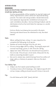
INTRODUCTION READ INSTRUCTIONS COMPLETELY BEFORE STARTING INSTALLATION It is the responsibility of the installer to meet all code and safety requirements, and to obtain all required building permits. The deck and railing installer should determine and implement appropriate installation techniques for each installation situation. Fortress Railing Products and its distributors shall not be held liable for improper or unsafe installations.
Required Tools Goggles T-25 Driver Bit Drill Safety Gloves #2 Phillips Head Bit Metal Cutting Miter Saw Tape Measurer Speed Square Drill Bits: 1/16”, 3/16”, 3/8”, [1.
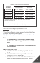
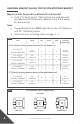
Universal Bracket (UB-04) Post Configuration Fe26 Traditional Panel Height Rail Panel Installed Panel Height* Required Post 34” [864mm] 37-3/4” [959mm] 39-1/2” [1003mm] 38” [965mm] 41-3/4” [1061mm] 45-1/2” [1156mm] 40” [1016mm] 43-3/4” [1111mm] 45-1/2” [1156mm] 40” [1016mm] 42” [1067mm] 45-1/2” [1156mm] *Installed panel heights include a 3-3/4” [95mm] space between deck surface and bottom edge of bottom rail.
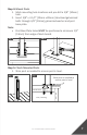
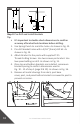
Fig. 1 Joist Blocking (A) (A) #10 x 3-1/3” [85mm] Step 2: Position Base Plate 1. Position the edge of base plate a minimum of 1/2” [13mm] from the inside edge of rim joist. As shown in Fig. 2. Fig. 2 1/2” [13mm] 1/2” [13mm] Step 3: Max Post Spacing • 6’ panel maximum post spacing is 69-3/4” [1772mm]. • 8’ panel maximum post spacing is 93-3/4” [2381mm]. • 10’ panel maximum post spacing is 117-3/4” [2985mm]. Note: • DO NOT exceed the maximum post spacing. Fig.
Step 5: Check Mounted Posts 1. Shim post as needed to ensure post is level. Shim post as needed to ensure post is level oud Post: Max Post Spacing m post spacing is 93-7/8”. m post spacing is 69-7/8”. Rim Joist 7 Fe26 TRADITIONAL INSTALLATION ceed the maximum post spacing. Check measurement with top Joist / Blocking m post spacing is 93-7/8”. m post spacing is 69-7/8”. 8’ Panel max post spacing 93-7/8” 6’ Panel max post spacing 69-7/8” ceed the maximum post spacing.
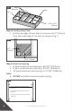
UNIVERSAL BRACKET (UB-04): POST W/ PRE-ATTATCHED BRACKET Step 1: Identify Required Pre-Attached Post & Bracket 1. Fe26 2” [51mm] and 3” [76mm] Posts are available with pre-attached UB-04 Brackets. Reference Fig. 8 & 9 below for desired post. Note: • Pre-welded posts are ONLY applicable to the 34” [864mm] and 40” [1016mm] panels. • Reference post mounting steps on pages 5 - 7. Fig.
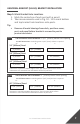
UNIVERSAL BRACKET (UB-04): BRACKET INSTALLATION Step 1: Mark Bracket Hole Locations 1. Mark the centerline of each post with a pencil. 2. Take measurements used in Fig. 10 - 12 to mark bottom and top bracket hole locations onto posts. Tip: • Fig. 10 Remove all metal shavings from deck, post base cover, post, and panel before bracket is screwed to post to prevent rust stains.
Fig. 12 B B C B A A B Step 2: Pre-Drill and Install Brackets Tip: • It’s important to double check dimensions to confirm accuracy of bracket hole locations before drilling. 1. Use Spring Punch to mark the holes. As shown in Fig. 13. 2. Pre-drill bracket holes with a 3/16” [5mm] drill bit. As shown in Fig. 14. 3. Attach Bracket to the posts with supplied T-25 Thread-Cutting Screws. Use two screws per bracket. Use low speed setting on drill. As shown in Fig. 15. 4.
Fig. 15 Fig. 16 UNIVERSAL BRACKET (UB-04): CUTTING DOWN PANEL Step 1: Measure The Panel Opening Length 1. Measure the distance of the panel opening. As shown in Fig. 17. Confirm that the measurements for the top brackets are the same as the bottom brackets. Note: • Measure from the back wall of the bracket to the back wall of the bracket on other post. As shown in Fig. 18. Fig. 17 Fig.
Step 2: Measure & Mark Panel Where Cuts Will Be Made 1. To ensure rails are symmetrical, take the measurement found in step 1 (Measure The Panel Opening Length), and divide it in half. 2. Find the center of the rails and measure out half of the length each direction. As shown in Fig. 19. 3. Mark these locations with a pencil on the top and bottom rail. Fig. 19 Mark Here Center of Panel Mark Here Half of Panel Length Mark Here Mark Here Step 3: Cut & Clean Panel 1.
3. Apply the 2nd coat of Fortress zinc based touch-up paint. 4. Allow to dry and install. Fig. 23 2X UNIVERSAL BRACKET (UB-04): PANEL INSTALLATION Step 1: Install I-Support On Bottom Rail 1. Measure and locate the center of the bottom rail. Using the I-Support as a guide, mark the center of the 2 screw holes. As shown in Fig. 24. 2. Using a 3/16” [5mm] drill bit, drill though the outside wall. 3. Install the I-Support with the provided Phillips Head Screws. As shown in Fig. 25.
Step 2: Install Panel 1. Install cut panel to ensure proper fit. Fig. 26 Step 3: Attach Panel To Bottom & Top Brackets 1. Pre-drill holes for screws using a 3/16” [5mm] drill bit. 2. Apply screws into bottom & top brackets. As shown in Fig. 27. Note: • Only one screw per bracket is needed to secure the bracket to the panel. • Screws should be installed on the same side of brackets. Fig. 27 Step 4: Attach I-Support To Deck 1. Fasten I-Support to deck surface with the supplied Phillips Head Wood Screw.
Fig. 28 POST BASE COVER, BRACKET CAP & PRESSED DOME/BALL CAP INSTALLATION Step 1: Install Post Base Cover 1. Separate the two-piece base plate cover. Hold one side parallel to the post base plate. As shown in Fig. 29. 2. Place 2nd half of the post base cover on the opposite side of the post. Hold 2nd piece slightly under the 1st piece. As shown in Fig. 30. 3. Twist the 2nd cover ¼ turn and move piece until both half’s touch. As shown in Fig. 31. 4.
Fig. 31 Fig. 32 Fig. 33 Step 2: Install Bracket Caps 1. Bracket Caps snap over Bracket Cups. As shown in Fig. 34 & 35. Fig. 34 Fig. 35 Step 3: Install Pressed Dome Cap 1. Pressed Dome Caps & Ball Caps are press fit into place. As shown in Fig. 36 & 37. 2. Use a broom or compressor to remove debris from railing and deck surface.
Fig. 36 Fig.
UNIVERSAL BRACKET WITH ACCENT TOP PANEL (ATP) Fe26 Traditional Universal (UB-04) Bracket with Accent Top Panel (ATP) Installation Option Pressed Dome Cap Ball Cap UB-04 Cap Accent Top Panel (ATP) UB-05 Cup UB-05 Cap Post Base Cover UB-04 Cup 3-3/4” [95mm] I-Support Fe26 Traditional Panel 6’, 8’ or 10’ 2” X 2” & 3” X 3” [1829mm, 2438mm [51mm x 51mm] or 3048mm] & [76mm x 76mm] Iron Posts With Base Universal Bracket With Accent Top Panel (ATP) Post Configuration Fe26 Traditional Panel Height Rail Pane
UNIVERSAL BRACKET WITH ATP: POST MOUNTING • Reference Post Mounting instructions on page 5. Note: It’s recommended to install brackets onto post before post mounting. UNIVERSAL BRACKET WITH ATP: BRACKET INSTALLATION Step 1: Mark Bracket Hole Locations 1. Mark the centerline of each post with a pencil. 2. Take measurements used in Fig. 38 and 39 to mark bracket hole locations onto posts.
Fig. 39 B Universal Bracket With ATP D B E A C B A B Step 2: Pre-Drill and Install Brackets • Reference Bracket hole pre-drilling and installation instructions on pages 10 & 11. UNIVERSAL BRACKET WITH ATP: CUTTING DOWN PANEL & ATP • Reference Panel and ATP cutting instructions on pages 11 - 13. UNIVERSAL BRACKET WITH ATP: PANEL INSTALLATION Step 1: Install I-Support On Bottom Rail • Reference I-Support to bottom rail instructions on page 13, step 1. Step 2: Install ATP Onto Panel 1.
Step 3: Install Panel 1. Install cut panel to ensure proper fit. As shown in Fig. 41. Fig. 41 Step 4: Attach Panel To Brackets • Reference panel to bracket instructions on page 14, step 3. Step 5: Attach I-Support To Deck • Reference I-Support to deck instructions on pages 14 & 15, step 4. POST BASE COVER, BRACKET CAP & PRESSED DOME/BALL CAP INSTALLATION • Reference Post Base Cover, Bracket Cap & Pressed Dome/ Ball Cap instructions on pages 15 - 17.
COLLAR BRACKET (CB-04) Fe26 Traditional Collar Brackets (CB-04) Installation Option Ball Cap CB-04 Pressed Dome Cap 3-3/4” [95mm] I-Support Fe26 Traditional Panel 6’, 8’ or 10’ [1829mm, 2438mm or 3048mm] Post Base Cover 2” X 2” & 3” X 3” [51mm x 51mm] & [76mm x 76mm] Iron Posts with base Collar Bracket (CB-04) Post Configuration Fe26 Traditional Panel Height Rail Panel Installed Panel Height* Required Post 34” [864mm] 37-3/4” [959mm] 39-1/2” [1003mm] 38” [965mm] 41-3/4” [1061mm] 45-1/2” [1156mm
COLLAR BRACKET (CB-04): POST MOUNTING • Reference Post Mounting instructions on page 5. COLLAR BRACKET (CB-04): BRACKET INSTALLATION Step 1: Mark Bracket Hole Locations 1. Mark the centerline of each post with a pencil. 2. Take measurements used in Fig. 42 and 43 to mark bracket hole locations onto posts. Tip: • Remove all metal shavings from deck, post base cover, post, and panel before bracket is screwed to post to prevent rust stains. Fig.
Step 2: Pre-Drill Bracket Holes • Reference Bracket hole pre-drilling instructions on page 10 (Step 2: 1 & 2). Note: • DO NOT install brackets in this step. COLLAR BRACKET (CB-04): CUTTING DOWN PANEL • Reference Panel cutting instructions on pages 11 - 13. Note: • When measuring the panel opening length for the CB-04 installation, measure from the inside face of each post.
Fig. 44 Fig. 45 Set Screw Step 3: Attach I-Support To Deck • Reference I-Support to deck instructions on pages 14 & 15, step 4. POST BASE COVER, BRACKET CAP & PRESSED DOME/BALL CAP INSTALLATION • Reference Post Base Cover, Bracket Cap & Pressed Dome/ Ball Cap instructions on pages 15 - 17.
COLLAR BRACKET WITH ACCENT TOP PANEL (ATP) Fe26 Traditional Collar Bracket (CB-04) with Accent Top Panel (ATP) Installation Option Pressed Dome Cap Ball Cap CB-04 Accent Top Panel (ATP) CB-05 Post Base Cover 3-3/4” [95mm] I-Support Fe26 Traditional Panel 6’, 8’ or 10’ 2” X 2” & 3” X 3” [1829mm, 2438mm [51mm x 51mm] or 3048mm] & [76mm x 76mm] Iron Posts With Base Collar Bracket (CB-04) With Accent Top Panel (ATP) Post Configuration Fe26 Traditional Panel Height Rail Panel With ATP Installed Panel Heig
COLLAR BRACKET WITH ATP: POST MOUNTING • Reference Post Mounting instructions on page 5. COLLAR BRACKET WITH ATP: BRACKET INSTALLATION Step 1: Mark Bracket Hole Locations 1. Mark the centerline of each post with a pencil. 2. Take measurements used in Fig. 46 and 47 to mark bracket hole locations onto posts. Tip: • Remove all metal shavings from deck, post base cover, post, and panel before bracket is screwed to post to prevent rust stains. Fig.
E Fig. 47 C A D Collar Bracket With ATP B A C C Step 2: Pre-Drill Bracket Holes • Reference Bracket hole pre-drilling instructions on page 10 (Step 2: 1 & 2). Note: • DO NOT install brackets in this step. COLLAR BRACKET WITH ATP: CUTTING DOWN PANEL • Reference Panel cutting instructions on pages 11 - 13. Note: • When measuring the panel opening length for the CB-04 installation, measure from the inside face of each post.
4. Secure Bracket onto Rails with provided T-25 Drive Thread-Cutting Screws. Use low speed setting on drill. As shown in Fig. 49. Fig. 48 Fig. 49 Set Screw Step 3: Attach I-Support To Deck • Reference I-Support to deck instructions on pages 14 & 15, step 4. POST BASE COVER, BRACKET CAP & PRESSED DOME/BALL CAP INSTALLATION • Reference Post Base Cover, Bracket Cap & Pressed Dome/ Ball Cap instructions on pages 15 - 17.
ANGLE BRACKET (UB-04 & CBS-04) Fe26 Traditional Angle Brackets Installation Options Universal Bracket Angle Adapter (UB-04) Ball Cap Pressed Dome Cap UB-04 Cap UB-04 Angle Adapter UB-04 Cup 2” [51mm] or 3-3/4” [95mm] I-Support Post Base Cover Fe26 Traditional Panel 6’, 8’ or 10’ [1829mm, 2438mm or 3048mm] 2” X 2” & 3” X 3” [51mm x 51mm] &[76mm x 76mm] Iron Posts with base Universal Bracket Angle Adapter (UB-04) Post Configuration Fe26 Traditional Panel Height Rail Panel Installed Panel Height* Requ
Universal Bracket Angle Adapter (UB-04) Angle Bracket Base UB-04 Bracket Cap Chicago Bolt Male Chicago Bolt Female UB-04 Bracket Cup Angle Bracket Adapter *Bracket & Stair adapters are sold separately.
Collar Bracket Side Adjustable (CBS-04) Chicago Bolt Female Angled Bracket Base Angle Collar Bracket Cup Chicago Bolt Male POST MOUNTING • Reference Post Mounting instructions on page 5. Note: IT’S RECOMMENDED TO INSTALL BRACKETS ON TO POST BEFORE POST MOUNTING. ANGLE BRACKET (UB-04 & CBS-04): BRACKET INSTALLATION Note: The bracket installation instructions cover both UB-04 and CBS-04, only use steps specific to bracket being installed. Step 1: Mark Bracket Hole Locations (UB-04 or CBS-04) 1.
Fig. 50 UB-04 Angle Adapter Bracket Hole Locations: 3-3/4” [95mm] Above Deck Spacing Pre-drill Dimensions: Pre-drilling with a 3/16” [5mm] drill bit is required B C A* 34” [864mm] Panel 4-1/4’” [108mm] 37-1/4” [946mm] 1-3/16” [30mm] 41-1/4” [1047mm] 1-3/16” [30mm] 43-1/4” [1099mm] 1-3/16” [30mm] 38” [965mm] Panel 4-1/4’” [108mm] 40” [1016mm] Panel 4-1/4’” [108mm] *Dimension A positions bottom edge of rail 3-3/4” [95mm] above deck surface.
Fig. 53 Collar Bracket Side Adjustable (CBS-04) Bracket Hole Locations Pre-drill Dimensions: Pre-drilling with a 3/16” [5mm] drill bit is required B C A* 34” [864mm] Panel 3-3/16’” [81mm] 30-11/16” [780mm] 2-5/16” [59mm] 34-3/4” [882mm] 2-5/16” [59mm] 36-3/4” [933mm] 2-5/16” [59mm] 38” [965mm] Panel 3-3/16’” [81mm] 40” [1016mm] Panel 3-3/16’” [81mm] *Dimension A positions bottom edge of rail 3-3/4” [95mm] above deck surface. *Dimension A is measured from the bottom surface of post base. Fig.
Fig. 56 1-3/16” [30mm] Center of Post Fig. 55 Pre-Drill with a 3/16” [5mm] drill bit Fig. 57 2-15/16” [75mm] Center of Post UB-04 Angle Adapter Pre-Drill with a 3/16” [5mm] drill bit CBS-04 Angle Bracket Step 3: Install UB-04 Angle Adapter 1. Attach Angle Adapter Base piece to the posts with supplied T-25 Thread-Cutting Screws. Use low speed setting on drill. As shown in Fig. 58. 2. Assemble Angle Adapter Body piece & Base piece. As shown in Fig. 59. 3.
Fig. 60 Step 4: Install CBS-04 Angle Brackets 1. Attach Angle Bracket Base piece to the posts with supplied T-25 Thread-Cutting Screws. Use low speed setting on drill. As shown in Fig. 61. 2. Assemble Angle Bracket Body piece & Base piece. As shown in Fig. 62. Tip: • Use a Bit Extender for an easier drilling process. Fig. 61 Fig. 62 Step 5: Determine Panel Length 1. Check to ensure that all posts are square and straight. Shim posts as required. 2.
Fig. 63 UB-04 Angle Bracket CBS-04 Angle Bracket Fig. 64 DO NOT measure from post Measure from back of bracket UB-04 Angle Bracket Fig. 65 DO NOT measure from post Measure from back of bracket CBS-04 Angle Bracket ANGLE BRACKET: CUTTING DOWN PANEL • Reference Panel cutting instructions on pages 11 - 13. ANGLE BRACKET: PANEL INSTALLATION • • Reference UB-04 Panel installation instructions on pages 13 - 15. Reference CB-04 Panel installation instructions on pages 24 - 25.
POST BASE COVER, BRACKET CAP & PRESSED DOME/BALL CAP INSTALLATION • 38 Reference Post Base Cover, Bracket Cap & Pressed Dome/ Ball Cap instructions on pages 15 - 17.
UNIVERSAL BRACKET ANGLE ADAPTER WITH ACCENT TOP PANEL (ATP) Fe26 Traditional Angle Universal Bracket with Accent Top Panel (ATP) Installation Option Ball Cap UB-04 Cap Accent Top Panel (ATP) UB-05 Cap Pressed Dome Cap UB-04 Angle Adapter UB-04 Cup UB-05 Angle Adapter UB-05 Cup 3-3/4” [95mm] I-Support Post Base Cover Fe26 Traditional Panel 6’, 8’ or 10’ [1829mm, 2438mm or 3048mm] 2” X 2” & 3” X 3” [51mm x 51mm] &[76mm x 76mm] Iron Posts with base Universal Bracket Angle Adapter (UB-04) Post Configu
UNIVERSAL BRACKET ANGLE ADAPTER WITH ATP: INSTALLATION • • Fig. 66 Reference Universal Bracket With Accent Top Panel (ATP) installation instructions on pages 18 - 21. Reference Fig. 66 & 67 below for bracket hole locations.
COLLAR BRACKET SIDE ADJUSTABLE (CBS-04) WITH ACCENT TOP PANEL (ATP) Fe26 Traditional Collar Bracket Side Adjustable (CBS-04) with Accent Top Panel (ATP) Installation Option Pressed Dome Cap Ball Cap CBS-04 Accent Top Panel (ATP) CBS-05 Post Base Cover 3-3/4” [95mm] I-Support Fe26 Traditional Panel 6’, 8’ or 10’ 2” X 2” & 3” X 3” [1829mm, 2438mm [51mm x 51mm] or 3048mm] & [76mm x 76mm] Iron Posts With Base Collar Bracket Side Adjustable (CBS-04) With Accent Top Panel (ATP) Post Configuration Fe26 Tr
COLLAR BRACKET SIDE ADJUSTABLE (CBS-04) WITH ATP: INSTALLATION • • • Reference Collar Bracket With Accent Top Panel (ATP) installation instructions on pages 26 - 29. When measuring panel opening length, measure from back of bracket, DO NOT measure from the inside face of post. As shown in Fig. 65 on page 37. Reference Fig. 68 & 69 below for bracket hole locations. Fig.
STAIR BRACKET Fe26 Traditional Stair Bracket Installation Options Universal Bracket (UB) Stair Adapter Ball Cap UB-04 Cap Pressed Dome Cap UB-04 Stair Adapter & Cup 2” X 2” & 3” X 3” [51mm x 51mm] & [76mm x 76mm] Iron Posts with Base Cover Collar Bracket (CB) Stair Ball Cap Pressed Dome Cap CB-04 Stair Bracket 2” X 2” & 3” X 3” [51mm x 51mm] & [76mm x 76mm] Iron Posts with Base Cover Fe26 TRADITIONAL INSTALLATION 43
Universal Bracket (UB) Stair Adapter Stair Bracket Base Stair Bracket Cap Chicago Bolt Male Chicago Bolt Female Stair Bracket Cup Stair Bracket Adapter *Bracket & Stair adapters are sold separately. Collar Bracket (CB) Stair Stair Bracket Base Chicago Bolt Male Stair Bracket Cup Chicago Bolt Female Note: The stair bracket installation instructions cover both UB-04 and CB-04, only use steps specific to bracket being installed.
Fig. 70 Fig. 72 UB-04 Stair Bracket Fig. 71 Fig. 73 CB-04 Stair Bracket Step 2: Bottom Bracket Installation Continued (UB or CB) 1. Use Spring Punch to mark the holes. As shown in Fig. 74. 2. Drill out bracket hole with a 3/16” [5mm] drill bit. As shown in Fig. 75. 3. Use T-25 screws to attach the UB or CB base to the post. Begin with top hole then bottom. As shown in Fig. 76. 4. Keep bracket base centered as you install second screw. 5.
Fig. 74 Fig. 76 Fig. 75 Fig. 77 UB-04 Stair Bracket Fig. 78 Fig. 79 UB-04 Stair Bracket CB-04 Stair Bracket Step 3: Top Bracket Installation 1. Position wood 2” x 4” (actual 1-1/2” x 3-1/2” [38mm x 89mm]) on stairs in line with bottom brackets. As shown in Fig. 80. 2. Place panel on top of wood 2” x 4” (actual 1-1/2” x 3-1/2” [38mm x 89mm]) next to bottom brackets. As shown in Fig. 81. 3. Rake the panel level until and positioned as close to final installation position as possible.
4. Clamp the panel to the post. Be sure to clamp at four touch points to keep panel in position. As shown in Fig. 82. 5. Position bracket parallel with top rail & flat centered on post. Make sure inside bottom of bracket is flush with bottom of rail. As shown in Fig. 83. 6. Use pencil to mark top edge of bracket location on post. 7. Dis-assemble the bracket by removing the barrel and screw. Reference the bracket options on page 44. 8. Place Bracket Base on previous top edge mark.
Fig. 82 Clamp Fig. 83 Clamp Clamp Mark top and bottom location of Stair Bracket on post Position bottom of Bracket flush with bottom of rail Clamp Fig. 84 Step 4: Top Bracket Installation Continued • Reference bottom bracket installation step 2 on pages 44 & 45. STAIR BRACKET: POST MOUNTING • Reference Post Mounting instructions on page 5. Note: It’s recommended to install brackets on to post before post mounting.
3. Have the panel raked and as close to final installation position as possible. 4. Confirm that panel is level. 5. Place cut marking on rails in line with the back of bracket opening. Be sure bottom of bracket and bottom of rail are flush. As shown in Fig. 85. 6. Use speed square to ensure markings are perpendicular to panel. Fig. 85 Mark on rail from back of bracket Position inside bottom of cup flush with bottom face of rail Step 2: Cut & Clean Panel 1.
Step 3: Apply Spray Paint To Cut Areas 1. Using a piece of cardboard as a mask, apply the 1st coat of Fortress zinc based touch-up paint. 2. Allow to dry before applying second coat. 3. Apply the 2nd coat of Fortress zinc based touch-up paint. 4. Allow to dry and install. Fig. 89 2X STAIR BRACKET: PANEL INSTALLATION • Tip: • Reference panel installation steps 2 & 3 on page 14. Be sure to confirm that the raked panel is level.
STAIR BRACKET (SSB-04) Fe26 Traditional Stair Bracket Installation Option Simplified Stair Bracket (SSB-04) Ball Cap LT Bracket & Cap Pressed Dome Cap SB Bracket & Cap ST Bracket & Cap LB Bracket & Cap 2” X 2” & 3” X 3” [51mm x 51mm] & [76mm x 76mm] Iron Posts with Base Cover Simplified Stair Bracket Each bracket base of the SSB’s has a stamped letter marking on the outside face to show the bracket being used Back View Front View Each bracket cup of the SSB’s has a stamped letter marking on the insid
Simplified Stair Bracket (SSB-04): LT Stair Bracket Base Stair Bracket Cap Chicago Bolt Male Chicago Bolt Female Stair Bracket Cup Simplified Stair Bracket (SSB-04): SB Stair Bracket Base Chicago Bolt Male Chicago Bolt Female Stair Bracket Cap Stair Bracket Cup Simplified Stair Bracket (SSB-04): ST Stair Bracket Base Chicago Bolt Female Stair Bracket Cap Chicago Bolt Male Stair Bracket Cup Simplified Stair Bracket (SSB-04): LB Stair Bracket Base Chicago Bolt Male Chicago Bolt Female 52 Stair
STAIR BRACKET (SSB-04): BRACKET INSTALLATION Bracket Options • When installing SSB brackets, Identify the 4 brackets (LT, ST, LB and SB) by the letters stamped in each part. • Reference the installed panel image and the placement of each SSB bracket on page 51. Step 1: Bottom Bracket Installation 1. Position wood 2” x 4” (actual 1-1/2” x 3-1/2” [38mm x 89mm]) between posts. As shown in Fig. 90. 2. Position bottom brackets centered flat on post & wood 2” x 4” (actual 1-1/2” x 3-1/2” [38mm x 89mm]).
Fig. 92 Step 2: Bottom Bracket Installation Continued 1. Use Spring Punch to mark the holes. As shown in Fig. 93. 2. Drill out bracket hole with a 3/16” [5mm] drill bit. As shown in Fig. 94. 3. Use T-25 screws to attach the base to the post. Begin with bottom hole then top. As shown in Fig. 95. 4. Keep bracket base centered as you install second screw. 5. Insert barrel & screw to re-assemble bracket. 6. Tighten barrel & screw. As shown in Fig. 96.
Fig. 95 Fig. 96 Step 3: Top Bracket Installation 1. Position wood 2” x 4” (actual 1-1/2” x 3-1/2” [38mm x 89mm]) on stairs in line with bottom brackets. 2. Place panel on top of wood 2” x 4” (actual 1-1/2” x 3-1/2” [38mm x 89mm]) next to bottom brackets. As shown in Fig. 97. 3. Rake the panel until center upright is parallel to the post or level and positioned as close to final installation position as possible. 4. Clamp the panel to the post.
Fig. 97 Fig. 98 Clamp Clamp Fig. 99 Clamp Clamp Mark top and side location of Stair Bracket on post Position bottom of Bracket flush with bottom of rail Fig. 100 Step 4: Top Bracket Installation Continued • Reference bottom bracket installation step 2 on pages 53 & 54. Tip: • For both top brackets (LT & ST), install the top screw first.
STAIR BRACKET (SSB-04): POST MOUNTING • Reference Post Mounting instructions on page 5. Note: It’s recommended to install brackets on to post before post mounting. STAIR BRACKET (SSB-04): CUTTING DOWN PANELS • Reference panel cutting instructions on pages 47 - 49. STAIR BRACKET (SSB-04): PANEL INSTALLATION • Tip: • Reference panel installation steps 2 & 3 on page 14. Be sure to confirm that the raked panel is level.
CARE & MAINTENANCE Care And Maintenance Of Fortress Building Products Powder-Coated Products And Surfaces: • • • • After installation of your Fortress Building Product, clean powder-coated products and surfaces with a solution of warm water and non-abrasive, pH neutral detergent solution. Surfaces should be thoroughly rinsed after cleaning to remove all residues. All surfaces should be cleaned using a soft cloth or sponge. Examples of acceptable cleaners are Simple Green, dish soap and warm water.
Fe26 TRADITIONAL INSTALLATION 59
JOIN THE REVOLUTION. FortressBP.com | 866.323.4766 © 2022 Fortress Building Products. Unless otherwise noted, all proprietary names are trademarks of Fortress Iron, LP. All rights reserved.