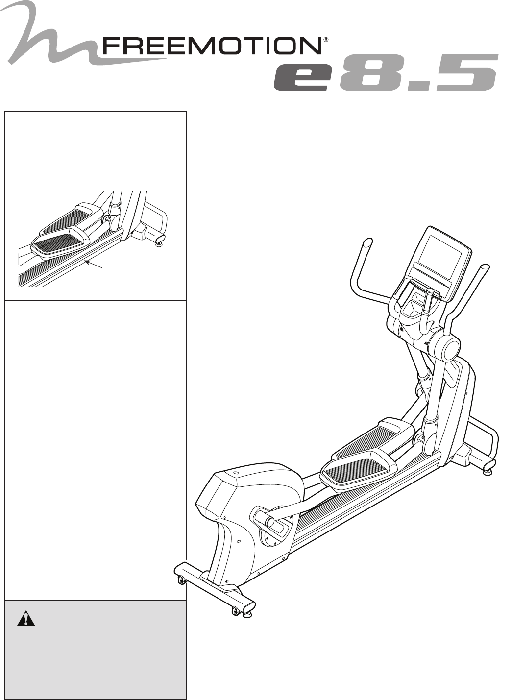
Model No. VMEL81914.0 Serial No. Write the serial number in the space above for reference. USER’S MANUAL Serial Number Decal QUESTIONS? If you have questions, or if parts are damaged or missing, please see HOW TO CONTACT CUSTOMER CARE on the back cover of this manual. CAUTION Read all precautions and instructions in this manual before using this equipment. Keep this manual for future reference. www.freemotionfitness.
TABLE OF CONTENTS WARNING DECAL PLACEMENT . . . . . . . . . . . . . . . . . . . . . . . . . . . . . . . . . . . . . . . . . . . . . . . . . . . . . . . . . . . . . . .2 IMPORTANT PRECAUTIONS . . . . . . . . . . . . . . . . . . . . . . . . . . . . . . . . . . . . . . . . . . . . . . . . . . . . . . . . . . . . . . . . . . 3 BEFORE YOU BEGIN. . . . . . . . . . . . . . . . . . . . . . . . . . . . . . . . . . . . . . . . . . . . . . . . . . . . . . . . . . . . . . . . . . . . . . . .
IMPORTANT PRECAUTIONS WARNING: To reduce the risk of burns, fire, electric shock, or injury to persons, read all important precautions and instructions in this manual and all warnings on your elliptical before using your elliptical. FreeMotion Fitness assumes no responsibility for personal injury or property damage sustained by or through the use of this product. 1. It is the responsibility of the owner to ensure that all users of the elliptical are adequately informed of all precautions. 9.
BEFORE YOU BEGIN Thank you for selecting the revolutionary FREEMOTION® E 8.5 elliptical. The E 8.5 elliptical provides an impressive selection of features designed to make your workouts more effective and enjoyable. manual. To help us assist you, note the product model number and serial number before contacting us. The model number and the location of the serial number decal are shown on the front cover of this manual. For your benefit, read this manual carefully before you use the elliptical.
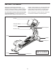
PART IDENTIFICATION CHART Use the drawings below to identify the small parts needed for assembly. The number in parentheses below each drawing is the key number of the part, from the PART LIST near the end of this manual. The number following the key number is the quantity needed for assembly. Note: If a part is not in the hardware kit, check to see if it has been preassembled. Extra parts may be included.
ASSEMBLY • Assembly requires two persons. • To identify small parts, see page 5. • Place all parts in a cleared area and remove the packing materials. Do not dispose of the packing materials until you finish all assembly steps. • Assembly can be completed using the included tools. Assembly may be easier if you have a set of wrenches. To avoid damaging parts, do not use power tools. • Left parts are marked “L” or “Left” and right parts are marked “R” or “Right.” 1.
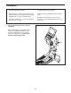
2. Identify the Left and Right Frame Covers (57, 60), and orient them as shown. 2 Hold the Left and Right Frame Covers (57, 60) together around the Frame (1) and the Upright (2). 71 71 Attach the Left and Right Frame Covers (57, 60) with eleven M5 x 12mm Screws (71) and two M5 x 10mm Truss Screws (73); start all the Screws, and then tighten them. 2 71 73 1 71 57 71 71 60 3. Attach the Top Frame Cover (58) to the Left and Right Frame Covers (57, 60) with an M5 x 12mm Screw (71).
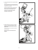
4. Orient the Right Upper Body Leg (26) assembly as shown. 4 Slide a Wave Washer (36) onto the right axle on the Upright (2). Then, slide the Right Upper Body Leg (26) onto the right axle. Attach the Right Upper Body Leg (26) with an M10 x 15mm Hex Screw (94), an M10 Split Washer (80), and an M10 Washer (93). Attach the Left Upper Body Leg (34) assembly in the same way. 2 36 34 93 80 94 26 5.
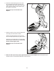
6. Attach the Knuckle Bearing (28) on the lower end of the Right Upper Body Leg (26) to the Right Pedal Arm (31) with an M10 x 75mm Bolt (108), two M10 x 20mm x 2mm Washers (95), and an M10 Locknut (96). 6 Repeat this step on the left side of the elliptical. 26 96 28 95 31 7. Identify a Left Pivot Cover (61) and a Right Pivot Cover (62), and orient them as shown. 95 108 7 Hold the Left and Right Pivot Covers (61, 62) around the Right Upper Body Leg (26) as shown.
HOW TO UPGRADE THE CONSOLE Your console has been preconfigured to operate with an optional digital TV. To learn about the features of the basic console, see page 14. To learn about the features of the digital TV, see the user’s manual included with the digital TV. The basic console has no television capabilities. To upgrade your console to include a digital TV whenever you choose, please see the back cover of this manual.
HOW TO USE THE ELLIPTICAL HOW TO PLUG IN THE POWER ADAPTER Plug the power adapter for the optional digital TV into the upper B digital TV power receptacle (B) on the frame of the elliptical. Then, plug the power adapter into an appropriate outlet that is properly installed in accordance with all local codes and ordinances The power adapter included with the elliptical must be used for the elliptical to operate.
HOW TO MOVE THE ELLIPTICAL HOW TO EXERCISE ON THE ELLIPTICAL Due to the size and weight of the elliptical, moving it requires two persons. Stand in front of the elliptical and lift the handle until the elliptical will roll on the rear wheels. Carefully move the elliptical to the desired location, and then lower it to the floor. To mount the elliptical, hold the upper body arms or the handlebars and step onto the pedal that is in the lower position. Then, step onto the other pedal.
WARRANTY INFORMATION All terms of the warranty are void if this product is moved beyond the continental borders of the United States of America (excluding Alaska, Hawaii, and Canada) and are then subject to the terms provided by that country’s local authorized FreeMotion Fitness, Inc. representative.
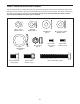
CONSOLE DIAGRAM FEATURES OF THE CONSOLE To activate the console, see page 15. To turn off the console, see page 15. To use the charging port, see page 15. The console offers an impressive array of features designed to make your workouts more effective and enjoyable. The console features a selection of onboard programs. Some programs automatically control the resistance of the pedals while guiding you through an effective exercise session.
HOW TO ACTIVATE THE CONSOLE HOW TO USE THE QUICK START MODE The power adapter must be used to operate the elliptical. See HOW PLUG IN THE POWER ADAPTER on page 11. When the power adapter is plugged in, the displays and indicators will light, a tone will sound, and the words SELECT PROGRAM OR QUICK START will scroll across the lower displays. 1. Turn on the console. See HOW TO ACTIVATE THE CONSOLE at the left. 2. Select the quick start mode. To select the quick start mode, press the Quick Start button.
Speed—This display will show your pedaling speed in miles or kilometers per hour. IMPORTANT: If you use both heart rate monitors at the same time, the console will not display your heart rate accurately. Note: The console can display speed in either miles per hour or kilometers per hour. To find which unit of measurement is selected, see step 4 on page 26. To use the handgrip heart rate monitor, follow the instructions below.
6. Pause the workout if desired. Average Speed—This display will show your average pedaling speed in miles per hour (MLH) or kilometers per hour (KMH). To pause the workout, press the Stop button. Note: If the pedals are not moved and no buttons are pressed for a short while, the console will exit the quick start mode or the program. Calories Burned—This display will show the approximate total number of calories (KCAL) you burned. To resume the workout, press the Quick Start button.
HOW TO USE AN ONBOARD PROGRAM During the program, the profile in the matrix will show your progress. The flashing segment of the profile represents the current segment of the program. The height of the flashing segment indicates the resistance level for the current segment. 1. Turn on the console. See HOW TO ACTIVATE THE CONSOLE on page 15. If the resistance level is too high or too low, you can manually override the resistance level by pressing the Level increase and decrease buttons. 2.
HOW TO USE THE GOAL PROGRAM If you selected a distance goal, the words ENTER DISTANCE will scroll across the lower displays. Press the numbered buttons to enter your desired distance goal. If necessary, press the Clear button to cancel your entry. When your distance goal is entered, press the Enter button. The program will then begin. 1. Turn on the console. See HOW TO ACTIVATE THE CONSOLE on page 15. 2. Select the goal program.
8. Follow your progress. 10. Pause the workout if desired. If you selected a time goal, the time display will count down until your time goal is reached. See step 6 on page 17. 11. End the workout and view the workout summary. If you selected a distance goal, the distance display will count down until your distance goal is reached. See step 7 on page 17. If you selected a calories goal, the calories display will count down until your calories goal is reached. 12. Exit the workout summary.
HOW TO USE THE HEART RATE CONTROL PROGRAM 5. Enter your age. The words ENTER AGE will scroll across the lower displays. Press the numbered buttons to enter your age. If necessary, press the Clear button to cancel your entry. When your age is entered, press the Enter button. 1. Turn on the console. See HOW TO ACTIVATE THE CONSOLE on page 15. 2. Wear a Polar-compatible chest heart rate monitor. 6. Enter a program time. The words ENTER TIME will scroll across the lower displays.
IMPORTANT: You cannot adjust the resistance of the pedals manually during the heart rate control program. 10. End the workout and view the workout summary. See step 7 on page 17. The program will continue in this way until the last segment ends. 11. Exit the workout summary. 8. Follow your progress. See step 8 on page 17. 12. Turn off the console. See step 4 on page 15. 9. Pause the workout if desired. See HOW TO TURN OFF THE CONSOLE on page 15. See step 6 on page 17.
HOW TO USE THE WATTS PROGRAM IMPORTANT: The watts target is intended only to provide motivation. Make sure to exercise at an intensity that is comfortable for you. 1. Turn on the console. See HOW TO ACTIVATE THE CONSOLE on page 15. If the resistance level is too high or too low, you can manually override the resistance level by pressing the Level increase and decrease buttons. IMPORTANT: The resistance level will automatically adjust at the end of each segment. 2. Select the watts program.
HOW TO USE THE FITNESS TEST During the fitness test, the console will automatically adjust the resistance of the pedals. 1. Turn on the console. IMPORTANT: You cannot adjust the resistance of the pedals manually during the fitness test. See HOW TO ACTIVATE THE CONSOLE on page 15. The program will continue in this way until the last segment ends. 2. Wear a Polar-compatible chest heart rate monitor. 7. Follow your progress.
FITNESS TEST RESULTS CHARTS Male Test Result 5 4 3 2 1 Excellent Good Average Fair Poor 5 4 3 2 1 Excellent Good Average Fair Poor Female Test Result 25
HOW TO CHANGE CONSOLE SETTINGS 4. Change settings as desired. 1. Turn on the console. The following settings can be changed: Language—The selected language will appear in the displays. The console will display text messages in the selected language. See HOW TO ACTIVATE THE CONSOLE on page 15. 2. Select the settings menu. Sleep Mode—The selected sleep mode setting will appear in the displays. To have the console stay on continuously, select ON.
COMPLIANCE INFORMATION UNITED STATES FCC Statement. This equipment has been tested and found to comply with the limits for a Class B digital device, pursuant to Part 15 of the FCC Rules. These limits are designed to provide reasonable protection against harmful interference in a residential installation. This equipment generates, uses, and can radiate radio frequency energy and, if not installed and used in accordance with the instructions, may cause harmful interference to radio communications.
MAINTENANCE AND TROUBLESHOOTING MAINTENANCE See assembly step 7 on page 9. Remove the Left and Right Pivot Covers (61, 62) from the Right and Left Upper Body Legs (26, 34). Inspect and tighten all parts of the elliptical regularly. Replace any worn parts immediately. Next, load a grease gun (not included) with high-quality multi-purpose extreme-pressure (EP) grease (not included). To clean the elliptical, use a damp cloth and a small amount of mild soap.
ADJUSTING THE DRIVE BELT Next, locate the M8 Locknut (90) on the Eyebolt (8). Tighten the Locknut until the Drive Belt (16) is tight. If the pedals slip while you are pedaling, even while the resistance is adjusted to the highest setting, the drive belt may need to be adjusted. Before you adjust the drive belt, unplug the power adapter. Remove the two Screw Caps (55) from the Shield Cover (54). Next, remove the two indicated M5 x 12mm Truss Screws (68). Then, remove the Shield Cover.
EXERCISE GUIDELINES Burning Fat—To burn fat effectively, you must exercise at a low intensity level for a sustained period of time. During the first few minutes of exercise, your body uses carbohydrate calories for energy. Only after the first few minutes of exercise does your body begin to use stored fat calories for energy. If your goal is to burn fat, adjust the intensity of your exercise until your heart rate is near the lowest number in your training zone.
PART LIST Key No. Qty. 1 2 3 4 5 6 7 8 9 10 11 12 13 14 15 16 17 18 19 20 21 22 23 24 25 26 27 28 29 30 31 32 33 34 35 36 37 38 39 40 41 42 43 44 45 46 47 48 49 50 1 1 1 1 1 1 1 1 1 2 2 2 2 1 4 1 4 2 1 2 3 2 1 1 1 1 2 2 1 4 1 1 4 1 1 2 1 2 2 2 2 8 2 2 1 1 1 1 1 2 Model No. VMEL81914.0 R0415A Description Key No. Qty.
Key No. Qty. 101 102 103 104 105 106 107 108 109 110 111 112 113 114 115 116 117 118 119 120 121 122 123 124 125 126 3 1 2 1 12 12 1 2 1 3 4 1 1 2 2 1 1 1 1 1 2 2 12 12 8 4 Description Key No. Qty.
144 141 149 3 133 92 116 148 18 17 91 89 138 142 90 145 143 84 129 137 7 129 130 86 129 68 24 6 87 23 132 83 128 9 125 125 134 87 73 101 88 5 110 8 104 90 44 150 140 21 1 102 150 112 21 67 118 70 96 117 146 81 80 113 95 99 15 2 115 114 72 119 121 85 12 122 109 10 100 98 114 103 95 115 14 120 122 98 4 150 147 129 103 139 150 96 129 107 11 100 80 16 98 100 73 135 99 123 111 82 73 13 EXPLODED DRAWING A M
37 20 78 38 35 22 78 34 34 56 97 39 93 80 32 126 80 40 94 136 126 77 96 95 30 33 28 42 42 41 42 93 33 95 27 77 76 42 76 26 36 123 79 80 94 106 124 105 127 106 20 43 105 94 25 80 29 93 108 30 19 22 106 31 124 EXPLODED DRAWING B Model No. VMEL81914.
131 35 68 124 75 68 75 131 75 68 53 66 65 66 55 68 68 131 64 52 54 61 68 68 51 55 71 71 131 75 68 75 62 63 50 71 48 71 68 69 55 71 57 49 74 59 73 68 68 58 50 71 74 68 68 46 71 71 71 61 71 73 60 51 68 47 45 62 68 52 63 71 71 EXPLODED DRAWING C Model No. VMEL81914.
HOW TO CONTACT CUSTOMER CARE If you have questions after reading this manual, or if parts are damaged or missing, please contact Customer Care at one of the phone numbers or addresses listed below. Please note the model number, serial number, and name of the product (see the front cover of this manual) before contacting Customer Care. If you are ordering replacement parts, please also note the key number and description of each part (see the PART LIST and the EXPLODED DRAWING near the end of this manual).