
- Using the ASB520 MC68HC908QT2 Based Infrared Remote Control Reference PC Board Designer Reference Manual

DRM045 Using the ASB520 MC68HC908QT2 Based Infrared Remote Control Reference PC Board
26 System Testing MOTOROLA
System Testing
6.4 LED and Push Button Test Code
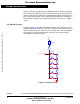
Test code is embedded in the ASB520 control program. This test code will test
the switches, LED drive circuitry and visible LED, D2. The infrared led, D1, is
illuminated, but you can’t see it. To run the test program, follow the next 12
steps:
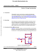
1. Connect a jumper lead between pins 2 and 6 on connector J1.
2. Install shorting jumpers on jumper blocks JP1–JP4
3. Install 3-AA Alkaline batteries into the battery holder mounted on the
bottom of the PC board. Note battery polarity on the battery holder.
When the last battery is installed, you will see the red LED, D2, flash five
times.
4. Depress the POWER switch, SW1. The red LED will flash once, delay
for approximately 2 seconds, flash again and continue that sequence
until the button is released. You will note the POWER button is SW1;
thus one blink. (This is the sequence for the remainder of the switches.)
5. Depress the PAUSE switch, SW2. The red LED will flash twice, delay for
approximately 2 seconds, flash twice again and continue that sequence
until the button is released.
6. Depress the PLAY switch, SW3. The red LED will flash three times,
delay for approximately 2 seconds, flash three times again and continue
that sequence until the button is released.
7. Depress the REVERSE switch, SW4. The red LED will flash four times,
delay for approximately 2 seconds, flash four times again and continue
that sequence until the button is released.
8. Depress the STOP switch, SW5. The red LED will flash five times, delay
for approximately 2 seconds, flash five times again and continue that
sequence until the button is released.
9. Depress the FORWARD switch, SW6. The red LED will flash six times,
delay for approximately 2 seconds, flash six times again and continue
that sequence until the button is released.
10. Remove one battery. It doesn’t matter which one.
11. Remove the jumper lead from connector J1.
12. Replace the battery. (The system is now in user mode.)
All hardware except for the infrared diode, D1, has been tested at this point.
Frees
cale Semiconductor,
I
Freescale Semiconductor, Inc.
For More Information On This Product,
Go to: www.freescale.com
nc...