Service and Parts Manual 2 0 11 SPLIT TYPE ROOM AIR CONDITIONER WALL MOUNTED TYPE Models Indoor Unit MW09C1H MW12C1H Outdoor Unit MR09C1H MR12C1H
Table of Contents Model and product code .................................................................................................. 3 Summary and features ......................................................................................................... 4 1. Safety Precautions ............................................................................................................... 5-7 2. Specifications .....................................................................................
Model and product code Model and product code Voltage range Complete unit model Indoor unit model Outdoor unit model 115V ~ 60H zM M09CIH MW09CIH MR09CIH 115V ~ 60H zM M12CH MW12CIH MR12CIH 3
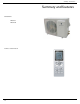
Summary and features Summary and features OutdoorUnit MR09CI H MR012CIH Remote control windo w YB1FAF 4
IMPORTANT SAFETY INFORMATION T h e i n f o r m a t i o n c o n t a i n e d i n t h i s m a n u a l i s i nt e n d e d f o r u s e by a q u a l i f i e d s e r v i c e technician who is familiar with the safety procedures required for installation and repair, and who is equipped with the proper tools and test instruments required to ser vice this product.
• Do not spray or pour water on the return air grille, discharge air grille, evaporator coil, control panel, and sleeve on the room side of the air conditioning unit while cleaning. • Electrical component malfunction caused by water could result in electric shock or other electrically unsafe conditions when the power is restored and the unit is turned on, even after the exterior is dry. • Never operate the A/C unit with wet hands.
PROPERTY DAMAGE HAZARDS FIRE DAMAGE HAZARDS: • Read the Installation/Operation Manual for the air conditioning unit prior to operating. • Use air conditioner on a single dedicated circuit within the specified amperage rating. • Connect to a properly grounded outlet only. • Do not remove ground prong of plug. • Do not cut or modify the power supply cord. • Do not use extension cords with the unit. • Be extremely careful when using acetylene torch and protect surrounding property.
2.
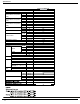
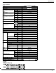
Specifications 12K of 115V Models Model Function Rated Voltage Frequency (Inverter different Compressor speed) Total Capacity (Inverter different Compressor speed) Power Input (Inverter different Compressor speed) Rated Input Rated Current Air Flow Volume Outdoor Unit MR12CH - SYSTEM MW12CIH High Standard Low High Standard Low High Standard Low High Standard High Standard Turbo SH H M L Dehumidifying Volume EER / C.O.
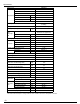
Specifications Outdoor Unit MR09C1H Manufacturer/trademark SANYO Model C-6RZ110H1A Type Twin rotory Compressor L.R.A. (A) A 33 RLA(A) A 4.59 Power Input(W) W 800 Overload Protector Int11l-3979 Electronic Expansion Valve throttling Transducer starting Throttling Method Starting Method Working Temp Range Heat Exchanger Coil F Coil Aluminum fin-copper tube Pipe Diameter mm .275 Rows-Fin Gap in. 2 - .005 Coil length (l) x height (H) x coil width (L) Speed Fan Motor 23.94 X 20 X 1.
Specifications Outdoor Unit MR12C1H Manufacturer/trademark SANYO Model C-6RZ110H1A Type Twin rotory Compressor L.R.A. (A) A 33 RLA(A) A 4.59 Power Input(W) W Overload Protector Throttling Method Starting Method Working Temp Range Heat Exchanger Coil 41 - 115 Aluminum fin-copper tube Pipe Diameter mm Rows-Fin Gap in. 2 - .005 mm 747X508X44 rpm 900/680 Speed .275 Output of Fan Motor W 40 RL A A 0.
Specifications Appending date Table showing operation frequency limits for cooling and heating Outdoor Relative Humidity 40% Outdoor Relative Humidity 72% 140 130 120 Indoor Wet Bulb Temperature( ) 59°F 68°F 110 77°F 100 80 60 40 Capacity Change Ratio (%) Capacity Change Ratio (%) 140 130 120 59°F 60.8°F Indoor Wet Bulb Temperature( ) 110 62.
Specifications Expanded c apacity data tables for both cooling and heating Cooling Capacity Ratio (%) 110 • Conditions DB80°F/WB67°F Indoor: DB80.06˚F/WB66.92˚F Indoor air flow : TURBO Pipe length : 7.6m 100 90 80 115 113 111 108 106 104 102 100 99 97 95 93 91 90 70 Outdoor temp.
Specifications Operation C haracteristic Curve Cooling • Conditions 25.0 22.5 Indoor: DB80°F/WB67°F Outdoor: DB95°F/WB75°F Indoor air flow : TURBO Pipe lengt: 7.6m 20.0 Current (A) 9 btu unit 17.5 15.0 12.5 10.0 7.5 115V 5.0 2.5 0 01 02 03 04 05 06 07 80 09 0 Compressor speed (rps) 1 2 K o12 f 11 5 Vunit U n i ts btu Cooling 25.0 22.5 Current (A) 20.0 • Conditions : Indoor: DB80°F/WB67°F Outdoor: DB95°F/WB75°F Indoor air flow : TURBO Pipe length: 7.6m 17.5 15.0 12.5 10.
Specifications 2.
Constrction views 3. Construction Views 3.1 Indoor Unit H W D 5 1 31/4 5 21 542 61 6 3/4 9 Unit:m m 3.
Refrigerant System Diagram 4.
Schematic Diagram 5. Schematic Diagram 5.1 Electrical Date Indoor Unit Symbol Color symbol Symbol WHITE WH Color symbol BROWN BN YE YELLOW BU BLUE RD RED BK BLACK YELLOW GREEN YEGN PROTECTIVE EARTH Outdoor Unit Symbol Parts name L1 REACROR PCB1~PCB2 S10/S11S40/S70/S80/S90 Symbol Color symbol WH WHITE PRINTED CIRCUIT BOARD YE YELLOW CONNECTOR RD RED SAT OVERLOAD BN SAT OVERLOAD BN BROWN COMP COMPRESSOR BU BLUE PROTECTIVE EARTH BK BLACK YELLOW GREEN YEGN 5.
Schematic Diagram Outdoor Unit Cooling Models of 115V COMP CT1,2 W10 RD W3YEGN R COMP E TUBE OUTROOM EXHUAST TEM.SENSOR TEM.SENSOR TEM.
Schematic Diagram 5.
Schematic Diagram TOP VIEW Terminal of jump wire, live wire and neutral wire, AC-N4 joint AC-N3, External connect highAC-L2 joint capacity positive terminal External connect highAC-L3 capacity negative Protective tube terminal Slug of on-off power High frequency transformer Stabilized voltage block 7805 IPM module Neutral wire terminal of 4-way valve Live wire terminal of 4-way valve Terminal of jumper wire, neutral wire Main relay Terminal of DC fan Terminal of compressor overload protector Disch
Function and Control 6. Function and Control 6.1 Remote Control Operations 1 2 START / STOP P res to s tart or s top operation. s ON/OFF Press it to start or stop operation : P ress to decrease temperature setting. MODE 3 : P res s to itincreas e temperature Press to select operation mode setting. (AUTO/COOL/DRY/FAN/HEAT) 4 AUTO FA N + : Press it to increase temperature P res s to s et fan s peed.
Function and Control 1 ON/OFF : Press this button to start the unit operation .Press this button again to stop the unit operation. 2 MODE : Each time you press this button,a mode is selected in a sequence that goes from AUTO, COOL,DRY, FAN,and HEAT * , as the following: FAN HEAT * COOL AUTO DRY *Note:Only for models with heating function. After energization, AUTO mode is defaulted.
Function and Control : 7 TIMER ON Press TIMER ON button, "ON" blinks and disappears. Within 5 seconds, every press of + or button increases or decreases the ON time setting by 1 minutes. Holding down either buton above 2.5 seconds rapidly changes the time setting by 1 minute and then by 10 minutes. Within 5 seconds after setting, press TIMER ON to confirm. To cancel the TIMER ON operation, press TIMER ON button. 8 TIMER OFF : Press TIMER OFF button to set TIMER OFF.
Function and Control 12 TURBO: Press this button in COOL or HEAT mode turns on/off Turbo function. After TURBO function is set, its icon is displayed. When switching operation mode or changing fan speed, this function will be canceled automatically. at super high fan speed. (This function is not applicable for some models). 13 SLEEP: Press SLEEP button into SLEEP operation. Press SLEEP button again to cancel SLEEP.
Function and Control Replacement of Batteries 1.Remove the battery cover plate from the rear of the remote controller. (As shown in the figure) 2.Take out the old batteries. 3.Insert two new AAA1.5V dry batteries, and pay attention to the polarity. 4. Replace the battery cover plate. ƾ Notes: ● When changing the batteries, do not use old or different batteries, otherwise, it may cause malfunction of the wireless remote control.
Function and Control 6.2 Description of Each Control Operation 1. Temperature Parameters Indoor preset temperature (Tpreset ) Indoor ambient temperature (Tamb.) 2. Basic Functions Once energized, in no case should the compressor be restarted within less than 3 minutes.
Function and Control Protection Protection is the same as that under the cooling mode. (3) Heating Mode Working conditions and process of heating If T amb.≤Tpreset+36°F, the unit enters heating mode, in which case the four-way valve, the compressor and the outdoor fan will operate simultaneously, and the indoor fan will run at preset speed in the condition of preset cold air prevention. If T amb.
Function and Control a. Under AUTO mode, if Tamb.≥Tpreset is detected, the unit will select to run under cooling mode, in which case implicit preset temperature is 77°F; if T amb.≤Tpreset 28°F, the compressor will stop, the outdoor fan will stop with a time lag of 1 minute, and the indoor fan will run at preset speed; and if Tpreset –(28°F )< Tamb.< Tpreset , the unit will remain at its original state. b. Under AUTO mode, if Tamb .
Function and Control Designation of sensors Faults The sensor is detected to be open-circuited or short-circuited for successive 30 Indoor ambient temperature seconds The sensor is detected to be open-circuited or short-circuited for successive 30 Indoor tube temperature seconds The sensor is detected to be open-circuited or short-circuited for successive 30 Outdoor ambient temperature seconds The sensor is detected to be open-circuited or short-circuited for successive 30 Outdoor tube temperature seconds
Function and Control Heating angle Cooling angle (10) Display Operation pattern and mode pattern display All the display patterns will display for a time when the unit is powered on, the operation indication icon will display in red under standby status. When the machine is start by remote controller, the indication icon will light and display the current operation mode (the mode light includes: Cooling, heating and dry). If you close the light key, all the display icons will close.
Function and Control 6.3 Detection of temperature sensor malfunction Detect malfunctions of temperature sensor any time. In defrosting period, the temperature sensor malfunction will not be detected. 5 min after finishing defrosting, the system begins to detect the temperature sensor malfunction. In other times, the temperature sensor malfunction will be detected. 1. When short-circuit occurs to the temperature sensor for 30s: The temperature sensor overheats.
Function and Control 6.7 Discharge Pipe Control Outline The discharge pipe temperature is used as the compressor’s internal temperature. If the discharge pipe temperature rises above a certain level, the operating frequency upper limit is set to keep this temperature from going up further.
Function and Control During cooling operation, the signals being sent from the indoor unit allow the operating frequency limitation and then prevent freezing of the indoor heat exchanger. (The signal from the indoor unit must be divided into the zones as the followings.) Detail Conditions for Start Controlling Judge the controlling start with the indoor heat exchanger temperature after 2 sec from operation start.
Function and Control Frequency PI control 0Hz 60sec. 50sec. Compressor Four way valve 600sec. 50sec. ON OFF ON OFF 5sec. Fan 5sec. ON OFF Electronic expansion valve opening 450pps 350pps 450pps Initial opening 6.12 Fan Control Outline Fan control is carried out according to the following priority. 1. Fan ON control for electric component cooling fan 2. Fan control when defrosting 3. Fan OFF delay when stopped 4. ON/OFF control in cooling operation 5.
Installation Manual 7. Installation Manual 7.1 Notices for installation Important Notices The unit installation work must be done by qualified personnel according to the local rules and this manual. Before installating, please contact with local authorized maintenance center, if unit is not installed by the authorized maintenance center, the malfunction may not solved, due to discommodious contacts.
Installation Manual Outdoor Unit Installation Position Selection Select a location from which noise and outflow air emitted by unit will not inconvenience neighbors, animals, plants. Select a location where there should be sufficient ventilation. Select a location where there should be no obstructions cover the inlet and outlet vent . The location should be able to withstand the full weight and vibration of the outdoor unit and permit safe installation.
Installation Manual 7.2 Installation dimension diagram Space to the ceiling 6 in. side above Space to the wall 6 in. to side 6 in. to side Space to the wall 10 ft. m fro nt f ro 6 ft. from bottom Air outlet side Space to the floor Space to the obstruction 12 in. side 19 in. top The dimensions of the space necessary for correct installation of the appliance including the minimum permissible distances to adjacent structures Air inlet side ck ba n.
Installation Manual 7.3 Installing Indoor Unit Installing Mounting Plate 1.Make the mounting plate completely level . As the water tray's oulet of the indoor unit is two-way type, the indoor unit during installation should slightly slant to watert tray's outlet for smooth drainage of condensing water. 2.Fix the mounting plate on the wall with screws.(Where is pre-covered with plastic granula) 3.
Installation Manual NOTE: All interconnecting wiring between indoor and outdoor unit must be performed by a a licenced electrical contractor The electric wiring must be correctly connected.Improper connection may cause spare parts malfunction. Tighten the terminal screws adequately to prevent loosening. After tightening the screws, slightly pull the wire and confirm whether it is firm or not. Ensure the electrical connections are properly earthed to prevent electrical shocks.
Installation Manual 7.4 Installing Outdoor Unit Electric wiring Disassemble the cable cross plate sub-assy on the outdoor unit right side plate. Take off wire clamp. Connect and fix power connect cord (for cooling and heating unit,connect and fix power connect cord and signal control wire)to terminal of line bank. Wiring should fit that of indoor unit.
Installation Manual 7.5 Check after Installation and Operation Test Check after Installation Items to be checked Possible malfunction Has it been fixed firmly? The unit may drop, shake or emit noise. Have you done the refrigerant leakage test? It may cause insufficient cooling(heating) capacity Is heat insulation sufficient? It may cause condensation and dripping. Is water drainage satisfactory? It may cause condensation and dripping.
Installation Manual 7.6 Installation and Maintenance of Healthy Filter(Optional) Installation of Healthy Filter 1. Lift up the front panel from the two ends of it, as the arrow direction shown. Then pull the air filter out. (as shown Fig.a) Fig. a 2. Attach the healthy filter onto the air filter, (as shown in Fig.b).. Fig. b Air filter Healthy filter 3. Mount the air filter properly along the arrow direction in Fig.c, and then close the panel cover. Fig.
Troubleshooting 9. Troubleshooting 9.1 Precautions before Performing Inspection or Repair Be cautious during installation and maintenance. Do operation following the regulations to avoid electric shock and casualty or even death due to drop from high altitude. * Static maintenance is the maintenance during de-energization of the air conditioner. For static maintenance, make sure that the unit is de-energized and the plug is disconnected.
Troubleshooting The breaker trips at once when it is set to "ON". Trip of breaker or blow of fuse The breaker trips in few minutes when it is set to "ON" Measure insulation resistance to grou nd to see if there is any leakage. The circuit or the part of the air conditioner has malfunction. They heat and break the insulation and lead to short circuit or creepage. Measure the insulation resistance or eliminate the malfunction one by one. If the breaker itself has malfunction, then replace the breaker.
Troubleshooting Improper set of temperature Adjust set temperature If cooling (heating) load is Check the forecasted load of cooling (heating) proper The refrigerant has leakage or is insufficient heck and fill the leakage, then vacuumize it and supplement the refrigerant as required Leakage between the high presMalfunction of refrigerant flow sure and the low pressure inside the compressor Malfunction of four-way valve Local block of capillary Poor COOL(HEAT) operation Replace the compressor Blo
Troubleshooting The fan does not run when it is set to supply air. In the cooling and heating mode, the compressor runs, but the outdoor fan does not run. The indoor fan motor is burned or breaks or has the heat protector malfunction. Replace the fan motor or the defective part. The built-in heat protector of the motor breaks frequently because the motor is abnormal. Replace the fan motor Wrong connection Make the correction connection based on the circuit drawing.
Troubleshooting In cool, heat mode, the outdoor unit and compressor will not run. Controller malfunction (IC200 3 b r o k e n , creepage of parallel capacitor of relay loop,relay is broken etc.) Change controller Wire loose or wrong connection Correctly wire according to the drawing Improper setting of temperature Adjust setting temp. Drainage pipe blocked or broken Change drainage pipe Wrap of refrigerant pipe joint is not close enough. Re-wrap and make it tight.
Troubleshooting If malfunction occurs,corresponding code will display and the unit will resume normal until protection or malfunction disappears.
Troubleshooting Name of running status Red light Green light Indoor unit display 1 Compressor start Blink once 2 Defrosting Blink twice 3 Anti-freezing protection Blink three times E2 4 IPM protection Blink four times H5 5 Overcurrent protection Blink five times E5 6 Overload protection Blink six times H4 7 Air exhaust protection Blink seven times E4 8 Overload protection Blink eight times H3 H1 9 Limited frequency (current) Blink once 10 Limited frequency (Air exhaus
Troubleshooting Analysis or processing of some of the malfunction display: 1. Compressor discharge protection Possible reasons: shortage of refrigerant; blockage of air filter; poor ventilation or air flow short pass for condenser; the system has noncondensing gas (such as air, water etc.
Troubleshooting 9.4 How to Check simply the main part Main Check Points: Units of 115V: Use AC voltmeter to check wether the voltage between terminal L and N on the wiring board is 115V AC Units of 115V: Whether the reactor ( L) is correctly connected? Whether the connection is loose or fallen? Whether the reactor (L) is damaged ? Fault diagnosis process: Switch on the unit and wait 1 minute Use DC voltmeter to measure the voltage on the two ends of electrolytic capacitor (test3) Voltage higher than 103.
Troubleshooting Mainly detect: Whether the connection between control panel AP1 and compressor COMP is secure? Whether loose? Whether the connection is in correct order? Whether the voltage input of the machine is within normal range? (Use AC voltmeter to measure the voltage between terminal L and N on the wiring board XT) Whether the compressor coil resistance is normal? Whether the insulation of compressor coil against the copper tube is in good condition? Whether the working loads of the machine are too
Troubleshooting Fault diagnosis process: Energize and switch on IPM protection occurs after the machine has run for a period of time? Y Use AC voltmeter to measure the voltage between terminal L and N on the wiring board XT) If the voltage between terminal L and N on wiring board XT is within 210VAC~250VAC? N Check the supply voltage and restore it to 210VAC~250VAC Y Start and run the unit.
Troubleshooting Mainly detect: Is outdoor ambient temperature in normal range? Are the outdoor and indoor fans operating normally? Is the heat dissipation environment inside and outside the unit is good? Overheat and high temperature protection Y Is outdoor ambient temperature higher than 53? Normal protection, please operate it after the outdoor ambient temperature is normalized. N 20 minutes after the complete unit is powered off.
Troubleshooting Mainly detect: Whether the compressor wiring is connected correct? Is time for compressor stopping enough? Is compressor broken? Power on the unit Is stop time of the compressor longer than 3 minutes? N Restart it up after 3 minutes Y Does startup fail? Y Are the wires for the compressor connected correctly? Is connection sequence right? N Connect the wires as per the connection diagram Y Replace the control panel AP1 N If the fault is eliminated? N Replace the compressor Y E
Troubleshooting Mainly detect: Whether the unit voltage is too high? Whether the work voltage is too low? Out of step occurs once the unit is powered on.
Troubleshooting Mainly detect: Whether the electronic expansion valve is connected well or not? Is electronic expansion valve damaged? Is refrigerant leaked? 20 minutes after the complete unit is powered off Is the terminal FA for the electronic expansion valve connected correctly? Connect the wires correctly Resistances between the first four pins close to the terminal hole and the fifth pin are almost the same, less than 100 ohm.
Troubleshooting Mainly detect: Check if the reactor (L) of the outdoor unit and the PFC capacitor are broken The failure diagnosis process is as follows: Start Check wiring of the reactor (L) of the outdoor unit and the PFC capacitor Whether there is any damage or short-circuit? Y Replace it as per the wiring diagram and reconnect the wires If the fault is eliminated? N Remove the PFC capacitor and measure resistance between the two terminals.
Troubleshooting Mainly detect: Detect the indoor and outdoor units connection wire and indoor and outdoor units inside wiring is connect well or not, if is there any damage? Is there any damage for the indoor unit mainboard communication circuit? Is communication circuit damaged? The flow chart for malfunction detect: Start Y Did the equipment operate normally before the failure occurs? N Check the wiring of the indoor and outdoor units with reference to the wiring diagram Check wiring inside of the i
Troubleshooting Start Measure voltage at the Test 10 position as shown in the diagram with a voltmeter Value jumping N Y Measure voltage at the Test 15 position as shown in the diagram with a voltmeter Y Value jumping N Y Fault with outdoor unit Measure voltage at the Test 11 position as shown in the diagram with a voltmeter Value jumping N Y Measure voltage at the Test 12 position as shown in the diagram with a voltmeter N Value jumping Y The communication circuit of the outdoor unit is nor
Troubleshooting (9) Flow chart for outdoor communitcation circuit detecting: 7HVW WKH YROWDJH EHWZHHQ 1 SRLQW RI ZLULQJ ERDUG DQG FRPPXQLFDWLRQ FDEOH ZLWK XQLYHUVDO PHWHU 7KH YROWDJH VKDOO EH YDULDEOH 2WKHUZLVH LW PLJKW EH PDOIXQFWLRQ RI PDLQERDUG RI LQGRRU XQLW RU PDOIXQFWLRQ RI PDLQERDUG RI RXWGRRU XQLW RU ZURQJ ZLUH FRQQHFWLRQ RI LQGRRU DQG RXWGRRU XQLW 3OHDVH HQVXUH WKDW WKHUH LV QR PDOIXQFWLRQ RI PDLQERDUG RI LQGRRU XQLW RU ZURQJ ZLUH FRQQHFWLRQ RI LQGRRU DQG RXWGRRU XQLW $IWHU UHPRYLQJ
Troubleshooting Troubleshooting Guide Appendix 1: form for indoor/outdoor unit's ambient sensor numerical value of resistance Temp. Resistance Temp. (°F) (°F) -2 0 1 3 5 7 9 10 12 14 16 18 19 21 23 25 27 28 30 32 34 36 37 39 41 43 45 46 48 50 52 54 55 57 59 61 63 64 66 68 70 72 73 75 77 79 81 82 84 86 88 90 91 93 95 97 99 100 102 104 106 108 109 111 113 115 117 118 120 122 124 126 127 130 131 133 135 136 64 Resistance Temp.
Troubleshooting Troubleshooting Guide Appendix 2: form for indoor/outdoor unit's tube temperature sensor numerical value of resistance Temp. Resistance Temp. Resistance Temp.
Troubleshooting Troubleshooting Guide Appendix 3: form for indoor/outdoor unit's air exhaust temperature sensor numerical value of resistance Temp. Resistance Temp. Resistance Temp. Resistance Temp.
Troubleshooting 9.5 2-way, 3-way Valve Appearance 2-way Valve (Liquid Side) Hexagonal wrench (4mm) Flare nut 3-way Valve (Gas Side) Valve cap Open position Flare nut Closed position Open position Closed position To piping connection To piping connection To outdoor unit Works Shipping 1.
Troubleshooting Liquid side Indoor unit Clsed Outdoor unit 2-way valve Gas side Clsed 3-way valve Vacuum pump Lo OPEN CLOSE * Procedure (1)Connect the charge hose from the manifold valve to the service port of the gas side packed valve. (2)Connect the charge hose to the port of the vacuum pump. (3) Open fully the low pressure side handle of the gauge manifold valve. (4)Operate the vacuum pump to begin evacuating.
Troubleshooting Liquid side Indoor unit 2-Way valve Open Outdoor unit Gas side Closed 3-Way valve Lo CLOSE CLOSE Purge the air • Procedure (1) Confirm that both the 2-way and 3-way valves are set to the open position. – Remove the valve stem caps and confirm that the valve stems (7) Immediately set the 3-way valve to the closed position. – Do this quickly so that the gauge ends up indicating 3 to 5kg/ cm2g. are in the raised position.
Troubleshooting Liquid side Indoor unit 3-Way valve Closed Outdoor unit Gas side Closed 3-Way valve Gas cylinder Lo R410A OPEN CLOSE • Procedure (1) Confirm that both the liquid side valve and the gas side valve are set to the closed position. (6) Disconnect the charge set and the gas cylinder, and set the Liquid side and Gas side valves to the open position. – Be sure to use a hexagonal wrench to operate the valve stems.
Troubleshooting Balance Refrigerant of the 3-way Valve (Gas leakage) Liquid side Indoor unit Outdoor unit 3-Way valve Open Gas side 3-Way valve Open Lo OPEN CLOSE • Procedure (1) Confirm that both the 2-way and 3-way valves are set to the back seat. (2) Connect the charge set to the 3-way valve’s port. – Leave the valve on the charge set closed. – Connect the charge hose to the service port.
Troubleshooting Evacuation (All amount of refrigerant leaked) Liquid side Indoor unit Outdoor unit 3-Way valve Open Gas side 3-Way valve Open Vacuum pump Lo OPEN CLOSE • Procedure (1) Connect the vacuum pump to the center hose of charge set center hose (2) Evacuation for approximately one hour. – Confirm that the gauge needle has moved toward -76 cmHg (vacuum of 4 mmHg or less).
Troubleshooting Gas Charging (After Evacuation) Liquid side Indoor unit 3-Way valve Open Outdoor unit Gas side Open 3-Way valve Check valve Charging cylinder Lo (1) OPEN CLOSE • Procedure \ (1) Connect the charge hose to the charging cylinder. – Connect the charge hose which you dis-connected from the vacuum pump to the valve at the bottom of the cylinder. – If you are using a gas cylinder, also use a scale and reverse the cylinder so that the system can be charged with liquid.
Removal Procedure 10. Removal Procedure 10.1 Removal Procedure of Indoor Unit Warning Be sure to wait 10 minutes or more after turning off all power supplies before disassembling work. Image shown here is indicative only. Actual product you receive may differ. front panel 1. Remove front panel Open the front panel and slightly pull it to remove it. filter 2. Remove guide louver Push out the shaft sleeve and slightly bend the guide louver to remove it. guide louver 3.
Removal Procedure clasps temp. sensor 4. Remove front case Unscrew the 6 tapping screws fixng the front panel and turn the front case backward to remove it. screws clasps 5. Remove electric box Unscrew the 2 screws fixing the electric box Pull out the wiring terminal of motor and then un- screw screw the 3 screws fixing electric box.Lift the electric box to remove it. 6. Remove evaporator Unscrew the screws on the rear pipe cardplate and then remove the cardplate.
Removal Procedure screws 7. Remove motor and cross flow fan Unscrew the screws fixing the motor press plate of motor and then the screws connecting the motor and cross flow fan to separate and remove them.
Removal Procedure 10.2 Removal Procedure of Outdoor Unit Cable Cross Plate sub-assy 1. Remove top cover and the Cable Cross Plate subassy Unscrew the screw on the handle and pull the Cable Cross Plate sub-assy forcibly downwards to re- top cover move it. Unscrew the 3 screws fixing the top cover to remove it. screws 2. Remove cabinet screws Unscrew the 4 screws fixing the cabinet to remove it. cabinet 3.
Removal Procedure 4. Remove electric box cover Unscrew the 2 screws fixing the electiric box. Pull theelectric box upwards and unplug the plug-in line to remove the electric box. screws 5. Remove axial flow fan Unscrew the nut and remove the washer fixing the axial flow fan and then pull it out. nut and washer axial flow fan 6.Remove 4-way valve Wrap the 4-way valve with wet cloth and unsolder the 4 weld spots of the 4-way valve to remove it.
Removal Procedure 7. Remove electronic expannsion valve Unsolder the weld spots of eletronic expansion valve connecting with other pipelines to remove it. electronic expannsion valve 8. Remove gas valve and liquid valve Unscrew the 2 screws fixing the gas valve and unsolder the weld spots of gas valve and suction pipe to remove the gas valve. Unscrew the 2 screws fixing the liquid valve and liquid valve screws unsolder the weld spots of liquid valve and suction pipe to remove the liquid valve.
SPLIT TYPE ROOM AIR CONDITIONER - WALL MOUNTED SYSTEM COMPONENTS 27 25 40 1 41 2 3 5 39 4 38 6 7 13 8 37 9 14 12 36 10 15 35 29 34 33 32 16 31 11 30 28 17 18 24 22 26 19 23 21 20 MW09C1H / MW12C1H Exploded Diagram 80
MW09C1H Parts List NO.
MW12C1H Parts List 82 NO.
SPLIT TYPE ROOM AIR CONDITIONER - WALL MOUNTED SYSTEM COMPONENTS 10 11 12 13 14 1 31 30 29 28 3 2 4 5 27 25 6 26 21 7 8 20 24 19 9 16 15 17 18 22 23 MR09C1H Exploded Diagram 83
MR09C1H Parts List NO.
SPLIT TYPE ROOM AIR CONDITIONER - WALL MOUNTED SYSTEM COMPONENTS 3 6 1 5 7 4 9 2 8 10 25 13 24 15 26 23 22 16 21 12 11 20 14 19 17 27 18 MR12C1H Exploded View 85
MR12C1H Parts List NO.
FRIEDRICH AIR CONDITIONING CO. 10001 Reunion Place, Ste. 500, San Antonio, TX 78216 (210) 546-0500 877-599-5665 x 261 FAX (210) 546-0630 Email: tac@friedrich.com www.friedrich.com Printed in the U.S.A.