Room Air Conditioner SVC MANUAL(General) CAUTION Before Servicing the unit, read the safety precautions in General SVC manual. Only for authorized service personnel.
Air Conditioner Service Manual CONTENTS Part 1 General Information 1. Safety Precautions........................................................................................................4 2. Nomenclature ...............................................................................................................7 Part 2 Functions & Controls 1. List of Functions & Controls........................................................................................9 2. Basic Mode Controls ................
Part 1 General Information 1. Safety Precautions ............................................................................................................4 2. Nomenclature......................................................................................................................
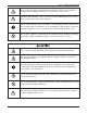
Part 1 General Information 1. Safety Precautions To prevent injury to the user or other people and property damage, the following instructions must be followed. ■ Incorrect operation due to ignoring instruction will cause harm or damage. The seriousness is classified by the following indications. This symbol indicates the possibility of death or serious injury. This symbol indicates the possibility of injury or damage to properties only. ■ Meanings of symbols used in this manual are as shown below.
Part 1 General Information Do not use a defective or underrated circuit breaker. Use the correctly rated breaker and fuse. Otherwise there is a risk of fire or electric shock. Install the panel and the cover of control box securely. Otherwise there is risk of fire or electric shock due to dust, water etc. Indoor/outdoor wiring connections must be secured tightly and the cable should be routed properly so that there is no force pulling the cable from the connection terminals.
Part 1 General Information 1.2 Inspections after Repair Check to see if the power cable plug is not dirty or loose. If the plug is dusty or loose it can cause an electrical shock or fire. Do not use a joined power cable or extension cable, or share the same power outlet with other electrical appliances. otherwise, it can cause an electrical shock, excessive heat generation or fire. Do not insert hands or other objects through the air inlet or outlet while the product is operating.
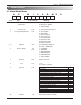
Part 1 General Information 2. Nomenclature 2.
Part 2 Functions & Controls 1. List of Controls & Functions ..........................................................................................9 2. Basic Mode Controls......................................................................................................10 3. Special Mode Controls...................................................................................................12 4. Utility Functions ......................................................................................
Part 2 Functions & Controls 1.
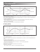
Part 2 Functions & Controls 2. Basic Mode Controls 2.1 Cooling Mode Thermo ON +0.5C(1F) Setting Temp. -0.5C(-1F) Thermo OFF INV. Comp. Frequency High Low Comp. OFF High Low • Operating frequency of compressor depends on the load condition, like the difference between the room temp. and the set temp., frequency restrictions. • If the compressor operates at some frequency, the operating frequency of compressor cannot be changed within 90 seconds.
Part 2 Functions & Controls 2.3 Healthy Dehumidification operation • When the dehumidification operation is set by the remote controller, the intake air temperature is detected and the setting temp. is automatically set according to the intake air temperature. Intake air Temp. Setting Temp. 26°C(78.8°F) ≤ intake air temp. 25°C(77°F) 24°C(75.2°F) ≤ intake air temp.< 26°C(78.8°F) intake air temp. -1°C(-2°F) 22°C(71.6°F) ≤ intake air temp. < 24°C(75.2°F) intake air temp. -0.5°C(-1°F) 18°C(64.
Part 2 Functions & Controls 3. Special Mode Controls 3.1 Jet Cool operation • In the heating mode or Auto Changeover operation, the Jet cool function does not work. When it is input while in other mode of operation (cooling, dehumidification, Air purification, Air circulation), the Jet cool operation takes place. • In the Jet cool mode, the indoor fan is operated at super-high speed for 30 min. at cooling mode operation.
Part 2 Functions & Controls 4. Utility Functions 4.1 Forced operation • To operate the appliance manually in case when the remote control is lost, the forced operation selection switch is on the main unit of the appliance, and operate the appliance in the standard conditions. • The operating condition is set according to the outdoor temp. and intake air temperature as follows. Indoor temp. Operating Mode Setting temp. over 24°C(75.2°F) Cooling 22°C(71.6°F) 21~24°C(69.8~75.
Part 2 Functions & Controls 4.3 Air volume control • UIndoor fan motor control have 6 steps or 8 steps. Step Description • UAir volume is controlled "SH", "H", "MH", "M", "ML", "L" by the remote controller. SL L ML M MH H SH Auto Super Low Low Medium-Low Medium Medium-High High Super High Natural Wind • "SL" step is selected in "Sleep Mode" operation. 4.
Part 2 Functions & Controls 4.6.2 Sleep timer operation for heating cycle • While in heating mode, 60 min. after the start of the sleep timer, the setting temperature decreases by 1°C(2°F). After another 60minutes lapse, it decreases again by 1°C(2°F). Setting temp. (°C) Heating ON temp. (Setting temp) 1.0°C(2°F) down 1.0°C(2°F) down Heating OFF temp. (Setting temp. +4.0°C(+8°F)) 1 2 Sleep time (hr) 4.
Part 3 Test Run 1. Check before Test Run...................................................................................................17 2. Test Run Flow chart .......................................................................................................18 3. Test Run Detail................................................................................................................
Part 3 Test Run 1. Check before Test Run 1 Check to see whether there is any refrigerant leakage, and check whether the power or transmission cable is connected properly. NOTE: Check that there should be no disconnection when all pins and wires are pulled by hands. Check whether the liquid pipe and gas pipe valves are fully opened. 2 NOTE: Be sure to tighten caps. Confirm that 500 V megger shows 2.0 MΩ or more between power supply terminal block and ground. Do not operate in the case of 2.0 MΩ or less.
Part 3 Test Run 2. Test Run Flow chart START Test operation for indoor unit Operate the unit in cooling mode. Does Test operation start? No Refer to part4, 6 Electric part Yes Is cold air discharged for more than 3 minutes ? No Yes Is there any temperature difference between intake and discharged air? Refer to part4, 5 Cycle part No Yes Is the operating current normal ? No Yes Operation mode change to Heating mode Is hot air discharged ? After Hot Start * Check the load (In/Out Temp.
Part 3 Test Run 3. Test Run Detail 1. Check that all tubing and wiring have been properly connected. NOTE: If the actual pressure is higher than shown, the system is most likely over-charged, and charge should be removed. If the actual pressure are lower than shown, the system is most likely undercharged, and charge should be added. 2. Check that the gas and liquid side service valves are fully open. 3. Check that all pins and wires have been connected thoroughly by pulling with hands.
Part 4 Trouble Shooting 1. 2-Way, 3-Way Valve ........................................................................................................21 2. Pumping Down ..............................................................................................................22 3. Evacuation (All amount of refrigerant leaked) ............................................................23 4. Gas Charging (After Evacuation) .................................................................................
Part 4 Trouble Shooting 1. 2-Way, 3-Way Valve 2-way Valve (Liquid Side) Hexagonal wrench (4mm) Flare nut 3-way Valve (Gas Side) Valve cap Open position Flare nut Closed position Open position Closed position To piping connection To piping connection Shipping 1.
Part 4 Trouble Shooting 2. Pumping Down Liquid side Indoor unit 2-Way valve Open Outdoor unit Gas side Closed 3-Way valve Lo CLOSE CLOSE Purge the air • Procedure (1) Confirm that both the 2-way and 3-way valves are set to the open position. – Remove the valve stem caps and confirm that the valve stems are in the raised position. – Be sure to use a hexagonal wrench to operate the valve stems. (6) Operate the air conditioner at the cooling cycle and stop it when the gauge indicates 1kg/cm2 .g.
Part 4 Trouble Shooting 3. Evacuation (All amount of refrigerant leaked) Liquid side Indoor unit Outdoor unit 3-Way valve Open Gas side 3-Way valve Open Vacuum pump Vacuum Gage Lo OPEN OPEN • Procedure (1) Connect the vacuum pump to the center hose of charge set center hose (2) Evacuation for approximately one hour. – Confirm that the gauge needle has moved toward 0.8 Torr.
Part 4 Trouble Shooting 4. Gas Charging (After Evacuation) Liquid side Indoor unit 3-Way valve Open Outdoor unit Gas side Open 3-Way valve Check valve Charging cylinder Vacuum Gage Lo (1) OPEN CLOSE • Procedure (1) Connect the charge hose to the charging cylinder. – Connect the charge hose which you dis-connected from the vacuum pump to the valve at the bottom of the cylinder.
Part 4 Trouble Shooting 5. Cycle Troubleshooting Guide Problem Possible causes Corrective action Error Code • There is a burning smell and a strange sound coming from the unit. Abnormal operating conditions. • Water leaks from the indoor unit even when the humidity level is low. • The power cord is damaged or generating excessive heat. • Turn off the air conditioner, unplug the power cord and contact the service center.
Part 4 Trouble Shooting Problem Possible causes Corrective action Error Code • Air is not circulatingprop- • Make sure that there are no curtains, blinds or furerly. niture blocking the front of the air conditioner. • The air filter is dirty. • Clean the air filter once every 2 weeks. • See “Cleaning Air Filter” for more information. summer, it may take some time to cool indoor air. • The room temperature is •• In In this case, select the jet cool operation to cool too high. indoor air quickly.
Part 4 Trouble Shooting Problem Possible causes Corrective action Error Code • The connection of the indoor and outdoor units has a problem. • Conduct the wiring and piping error check. 05, 09, 53 • The thermistor recognition has a defect. • Check that the thermistor have been separated from the pipe holder. 09, 32, 41, 45 • The electronic expansion valve operates incompletely. • Check the temperature of the connection 44, 61, 65 pipe.
Part 4 Trouble Shooting 6. Electronic Parts Troubleshooting Guide Trouble 1 The Product doesn’t operate at all. (9~30kBtu/h Model) Turn off the main power and wait until LED on outdoor PCB is off. Turn on the main power again. Does "Beeping" sound is made from the indoor unit? Does "Lighting" LED is mounted on the outdoor PCB? NO YES Check the voltage of power(AC 208~230V, 60Hz). • Primarily, the operating condition of Micom is O.K. • The voltage of main power. • The voltage applied to the unit.
Part 4 Trouble Shooting Trouble 2 Product doesn't operate with the remote controller. Turn on main power. While the compressor has been stopped, the compressor does not operate owing to the delaying function for 2 minutes after stopped. When the compressor stopped Indoor Fan is driven by a low speed. At this point the wind speed is not controlled by the remote controller. (When operated in the Sleeping Mode, the wind speed is set to the low speed as force).) Caused by the remote controller.
Part 4 Trouble Shooting Trouble 3 The Compressor/Outdoor Fan don't operate Turn on the main power. Operate Cooling Mode by setting the desired temperature of the remote controller is less than one of the Indoor temperature by 1°C at least. When in air circulation mode, compressor/outdoor fan is stopped. Check the sensor for Indoor temperature is attached as close as to be effected by the temperature of Heat Exchange (EVA.) When displaying Error code, refer to the trouble shooting guide.
Part 4 Trouble Shooting Trouble 4 When indoor Fan does not operate Turn off main power. Check the connection of CN-FAN. Check the Fan Motor. Check the Fuse(AC250V, T2A). Check the related circuit of indoor Fan Motor. • The pin No. 38 of micom and the part for driving SSR.(Q01M) • Check the related pattern. • Check the SSR. - SSR Open: Indoor Fan Motor never operate. - SSR short: Indoor Fan Motor always operates in case of ON or OFF. • Check the connectors.
Part 4 Trouble Shooting 7. Self-diagnosis Function ■ Error Indicator • The function is to self-diagnosis airconditioner and express the troubles identically if there is any trouble. • If more than two troubles occur simultaneously, primarily the highest trouble of error code is expressed. • After error occurrence, if error is released, error LED is also released simultaneously. • To operate again on the occurrence of error code, be sure to turn off the power and then turn on.
Part 4 Trouble Shooting 3.
Part 4 Trouble Shooting ■ Outdoor Unit Error 1) 2 LED Type LED1 (Green, 1 Digit) LED2 (Red, 10 Digit) Error Code 21 22 23 25 26 27 29 31 32 37 40 41 44 45 48 53 60 61 62 63 65 67 72 73 Error Indication Indoor Unit Outdoor Unit Description DC Peak (IPM Fault) CT 2(Max CT) DC Link Low Volt Low wire volt/ high wire volt DC Comp Position Error PSC Fault Error Inverter Compressor over-current CT error (low current) D-Pipe High (INV) Failure Compression Ratio CT Sensor (Open / Short) INV.
Part 4 Trouble Shooting 2) 1 LED Type Ex) Error Code 21 (DC Peak) Red LED 1sec Error Code 21 22 23 25 26 27 29 31 32 37 40 41 44 45 48 53 60 61 62 63 65 67 72 73 2sec 1sec 2sec 1sec 2sec 1sec 2sec Error Indication Indoor Unit Outdoor Unit Description DC Peak (IPM Fault) CT 2(Max CT) DC Link Low Volt Low wire volt/ high wire volt DC Comp Position Error PSC Fault Error Inverter Compressor over-current CT error (low current) D-Pipe High (INV) Failure Compression Ratio CT Sensor (Open / Short) INV.
Part 4 Trouble Shooting ■ Old Model Error Error Code Error Indication Indoor Outdoor Description Indoor Operation 1 Indoor Temperature Sensor Error - Suction Sensor open/short - Indoor Pipe Sensor open/short ● - Operation 2 Outdoor Temperature Sensor Error - Suction Sensor open/short - Outdoor Pipe Sensor open/short ● ● Operation 3 Humidity Temperature Sensor Error - Humidity Sensor short ● ● Operation 4 Heat Sink Temperature Sensor Error - Temperature Sensor open/short - Compressor-off
Part 4 Trouble Shooting ■ Troubleshooting Guide (Indoor Unit) - 37 -
Part 4 Trouble Shooting Check Method Measure resistance Check Point Refer to Check Point Resistance is adequate? 1. 10k Ω / at 25℃(77℉)±10% 2. 5k Ω / at 25℃(77℉)±10% 3. 200k Ω / at 25℃(77℉)±10% Yes Sensor OK No Replace Sensor ❏ Discharge Pipe Temp Sensor (200㏀) Resistance (White) 200~165㏀@25~30°C ❏ Air/Room Temp. Sensor (10㏀) Resistance (Black) 10~8㏀@25~30°C ❏ Indoor Pipe Temp. Sensor (5㏀) Resistance (Blue) 5~4㏀@25~30°C ❈ For more information, please refer to the 38 page table.
Part 4 Trouble Shooting Resistance - Temp. Sensor Table Temp (℃/℉) -30/-22 -25/-13 -20/-4 -15/5 -10/14 -5/23 0/32 5/41 10/50 15/59 20/68 25/77 30/86 35/95 40/104 45/113 50/122 55/131 60/140 65/149 70/158 75/167 80/176 90/194 100/212 Resistance(KΩ) Air Sensor s-Pipe Sensor D-Pipe Sensor 204.35 146.97 107.09 79 58.95 44.47 33.9 26.09 20.27 15.89 12.55 10 8.03 6.49 5.28 4.32 3.56 2.95 2.46 2.06 1.74 1.47 1.25 0.92 0.68 102.17 73.49 53.55 3950 29.48 22.24 16.95 13.05 10.14 7.94 6.28 5 4.01 3.24 2.64 2.
Part 4 Trouble Shooting Inspection Number Description of Inspection CH04 Float switch Cause of Error • Float switch open. (Normal : short) • Water over flow Check Point • The connection of wire (Float switch) • Indoor unit installation.
Part 4 Trouble Shooting (verify with hands) (verify with hands) - 41 -
Part 4 Trouble Shooting • Verify with hands certainly (pulling by hand to check connection status) • Verify with hands certainly (pulling by hand to check connection status) Pin and wire disconnection or pressed - • Verify with hands certainly (pulling by hand to check connection status) - - 42 - • Connect certainly • Repair or replace the harness. • Repair or replace the harness.
Part 4 Trouble Shooting ■ Trouble Shooting Guide [Outdoor Unit (2 LED Type)] 1) CH21: DC Peak Error caution Check that whether the housings and harness would be separated by pulling those with hands directly. • Remedy : replace PCB Assembly.
Part 4 Trouble Shooting Case of field defect ❏ IPM (Over Current Limit) ❏ Bending/Folding - 44 - ❏ SVC Valve close
Part 4 Trouble Shooting 2) CH22: CT2 Error (Input Over-current) caution Check that whether the housings and harness would be separated by pulling those with hands directly.
Part 4 Trouble Shooting 3) CH23: DC Link Low Voltage Error - 46 -
Part 4 Trouble Shooting 4) CH26: DC Comp Location Sensing Error caution Check that whether the housings and harness would be separated by pulling those with hands directly.
Part 4 Trouble Shooting 5) CH27: PSC Fault Over-current Error caution Check that whether the housings and harness would be separated by pulling those with hands directly.
Part 4 Trouble Shooting 6) CH29: Compressor phase Over-current Error (only verifiable at Outdoor unit PCB Assembly) caution Check that whether the housings and harness would be separated by pulling those with hands directly.
Part 4 Trouble Shooting 7) CH32: Inverter Compressor D-Pipe Overheat Error caution Check that whether the housings and harness would be separated by pulling those with hands directly.
Part 4 Trouble Shooting 8) CH40: CT Sensor Error (Open/Short) Tester Tester - 51 -
Part 4 Trouble Shooting 9) CH41/44/45/65: Inv D-Pipe/Outdoor Inlet/Cond.
Part 4 Trouble Shooting 10) CH53: Outdoor Unit <-> Indoor Unit Communication Error - 53 -
Part 4 Trouble Shooting 11) CH60: Outdoor Unit PCB EEPROM Error • Remedy : reassemble EEPROM / Replace PCB Assembly Check Method ڸ ڹ ں - 54 -
Part 4 Trouble Shooting 12) CH61: Cond. Pipe Overheat Error (Fan constraint, Heat exchanger contaminated caution Check that whether the housings and harness would be separated by pulling those with hands directly.
Part 4 Trouble Shooting 13) CH62: Heat Sink Overheat Error - 56 -
Part 4 Trouble Shooting 14) CH67: Outdoor BLDC Fan Lock Error Case of field defect ❏ BLDC Fan Motor (short) - 57 -
Part 4 Trouble Shooting ■ Trouble Shooting Guide [Outdoor Unit(1 LED Type)] 1) CH21: DC Peak Error caution Check that whether the housings and harness would be separated by pulling those with hands directly.
Part 4 Trouble Shooting Resistance between the lines of each 1.5 ~ 2 U-V 1.5 ~ 2 V-W 1.
Part 4 Trouble Shooting 2) CH22: CT2 Error (Input Over-current) caution Check that whether the housings and harness would be separated by pulling those with hands directly.
Part 4 Trouble Shooting 3) CH23: DC Link Low Voltage Error - 61 -
Part 4 Trouble Shooting 4) CH26: DC Comp Location Sensing Error caution Check that whether the housings and harness would be separated by pulling those with hands directly.
Part 4 Trouble Shooting 5) CH29: Compressor phase Over-current Error (only verifiable at Outdoor unit PCB Assembly) caution Check that whether the housings and harness would be separated by pulling those with hands directly.
Part 4 Trouble Shooting 6) CH32: Inverter Compressor D-Pipe Overheat Error caution Check that whether the housings and harness would be separated by pulling those with hands directly.
Part 4 Trouble Shooting 7) CH40: CT Sensor Error (Open/Short) Is AC input current sensing part normal? Check voltage measurement on the input current (Fig.1) at the power-on standby state DC 0V ± 0.2V Is the Comp phase Current sensor part normal? DC voltage measurement at the measurement point in figure 2 at power-on standby state -> measured value : within 2.5V ± 0.
Part 4 Trouble Shooting 8) CH41/44/45/65: Inv D-Pipe/Outdoor Inlet/Cond.
Part 4 Trouble Shooting 9) CH53: Outdoor Unit <-> Indoor Unit Communication Error - 67 -
Part 4 Trouble Shooting 10) CH60: Outdoor Unit PCB EEPROM Error - 68 -
Part 4 Trouble Shooting 11) CH61: Cond. Pipe Overheat Error Fan Heat exchanger contaminated caution Check that whether the housings and harness would be separated by pulling those with hands directly.
Part 4 Trouble Shooting 12) CH62: Heat Sink Overheat Error caution Check that whether the housings and harness would be separated by pulling those with hands directly.
Part 4 Trouble Shooting 13) CH67: Outdoor BLDC Fan Lock Error - 71 -
P/No : MFL41161608