INSTALLATION & OPERATION GUIDE PTAC PACKAGED TERMINAL AIR CONDITIONERS & HEAT PUMPS Standard Control Remote Thermostat Seacoast Protected 920-087-04 (8-05)
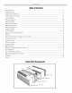
920-087-04 (8-05) Tableof Contents Unit Components ...............................................................................................................................................................................................2 Model Number Code ..........................................................................................................................................................................................3 Installation Recommendations ...............................
920-087-04 (8-05) Thank you for your decision to purchase the newly designed Friedrich Packaged Terminal Air Conditioner (PTAC). We are confident that you will find this unit a quiet and efficient example of Friedrich reliability. This Installation and Operation Manual has been designed to insure maximum satisfaction in the performance of your unit. For years of trouble-free service, please follow the installation instructions closely. We cannot overemphasize the importance of proper installation.
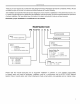
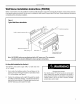
920-087-04 (8-05) PTACInstallation Recommendations For proper PTACunit performance and maximum operating life please refer to the minimum installation clearances below: FigureI PTAC units should be installed no closer than 12" apart when two units are side by side. If three or more PTAC units are to THREE OR MORE PTACs A.DJACENT 36" MINIMUM VIEW: OUTSIDE BUILDING ELEVATION operate next to one another allow a minimum of 36" between units.
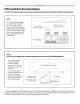
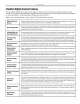
920-087-04 (8-05) FriedrichDigital Control Features The new Friedrich digital PTAC has state of the art features to improve guest comfort, indoor air quality and conserve energy. Through the use of specifically designed control software for the PTAC industry Ffiedfich has accomplished what other Manufacturer's have only attempted - a quiet, dependable, affordable and easy to use PTAC. Below is a list of standard features on every Friedrich PTAC and their benefit to the owner.
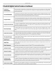
920-087-04 (8-05) FriedrichDigital ControlFeaturesContinued Instant Heat Heat Pump Mode Even Heat Monitoring Heatpumpmodelswill automaticallyruntheelectricheaterto quicklybringthe roomup totemperature when initiallyenergized, thenreturntoheatpumpmode.Thisensuresthattheroomis broughtup totemperaturequicklywithouttheusualdelayassociatedwithheatpumpunits. Thedigitalcontrolmonitorsindoorconditionstoensurethattheroomtemperatureiswithinfivedegreesofthe setpoint.
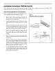
920-087-04 (8-05) Installation Instructions PXDRIO Drain Kit NOTE: Determine whether drain will be located within the wall, on the indoor side, or will drain to the exterior of the building. Follow appropriate instructions below depending on your particular type of installation. Internal Drain (optional for new construction) NOTE: If installing an internal drain, you MUST install a drain kit on the wall sleeve before the wall sleeve is installed.
920-087-04 (8-05) ExtemalDrain(for new constructionor unit replacement) When using an external drain system, the condensate is removed through either of two drain holes on the back of the wall sleeve. Select the drain hole which best meets your drainage situation and install the drain kit. Seal off the other with a cover plate. Drain Tube Installation Cover Plate Installation 1.
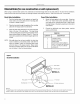
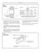
20-087-04 (8-05) Wall Sleeve Installation Instructions(PDXWS) NOTE: Insure that the unit is only installed in a wall structurally adequate to support the unit includingthe sleeve, chassis and accessories. If the sleeve projects more than 8" into the room, a subbase or other means of support MUST be used. Please read these instructions completely before attempting installation. Figure5 Typical Wall Sleeve Installation J 16W' Electrical receptacle Lintel to support masonry 10 _ (25.
920-087-04 (8-05) Figure6 Dimensions A Dimension* Allow for wall (6.4 cm) rain. (Minimum) With With T Wall Drill two 3/16" holes through each side of the sleeve approximately 4" from top and 4" from bottom of sleeve. Screw four #10 x 1" screws (included) or appropriate fasteners for your installation, through the holes in the sides of the wall sleeve. , Allow for floor Su bbase Lateral Duct Min. ¼" ¼" (6.4 mm)* (6.4 mm) 1¾" 3W' (4.5 cm) (8.9cm) ¾" ¼" (1.9 cm) (6.4 mm) --5" (12.
920-087-04 (8-05) Section II - Deep Wall Installation (PXWE) If the wall is thicker than allowed in the notes in Figure 6, a sheet metal wall sleeve extension and flashing MUST be used. Installation Instructions for the PXWE - 4" Wall Sleeve Extension The following points MUST be considered when installing a wall sleeve extension: 1 Provision must be made to direct excess condensate from the back of the wall sleeve into the extension then outside the building or to a drainage system. 2.
920-087-04 (8-05) Installation InstructionsModel PXGAStandard Grille 1. Remove the center support and weatherboard if still installed in the sleeve. 2. Insert six plastic grommets into the grille openings from the outside of the grille as shown in Figure 9. 3. Insert two #8 x 3/8" sheet metal screws (provided) in the top two outside edge plastic grommets, and tighten them halfway into the grommets. 5. Grasp the grille by the attached plastic handles.
920-087-04 (8-05) A. Electrical RatingTables All 230/208 volt units areequippedwithpowercords.See AppendixBon page19 forwiringinstructionson265V units. NOTE: Use Copper Conductors ONLY. Wire sizes are per NEC, check local codes for overseas applications.
920-087-04 (8-05) Installation Checklist [] Inspect all components and accessories for damage before and after installation. [] [] [] [] [] Ensure that the chassis is installed in a 16" high x 42" wide wall sleeve that is no deeper than 13 3/4". A baffle kit is required if the sleeve exceeds that depth. Remove the cardboard wall sleeve support and grille weatherboard. [] Check for proper wall sleeve installation in accordance with the wall sleeve installation instructions.
920-087-04 4. Center the chassis in the pre-installed sleeve and carefully push the chassis untilthe chassis flange and gasket contact the sleeve flange. ® (8-05) them into the quick nuts located on the chassis to secure the cover. If the unit has been placed such that there is no room to insert the thumbscrews from the bottom, request a Side Mounting kit (Part No. PXSM) from Friedrich. Locate the service cord or conduit in the notch at the bottom right of the front cover.
920-087-04 (8-05) Digital Control User Input Configuration The adjustable control dip switches are located at the lower left hand portion of the digital Smart Center. The inputs are only visible and accessible with the front cover removed from the PTAC. Dip Switch Setting 1) Electronic Temperature Limiting - Switches 1-4 The digital control is set from the factory to allow a temperature range between 60°F and 90°F in both heating and cooling mode.
920-087-04 (8-05) Digital ControlOperation TemperatureDisplay Figure12 The Ffiedfich digital PTAC is shipped from the factory to display the desired room temperature on the LED readout. Digital ControlPanel The unit can be configured to display the room temperature by simultaneously pressing the 'Cool' and 'High Fan' buttons for three seconds the display will show an 'F,"for one seconds to acknowledge the change.
920-087-04 (8@5) RemoteThermostatand LowVoltageControl Connections Remote Thermostat All Friedrich PD model PTAC units are factory configured to be controlled by either the chassis mounted Smart Center or a 24V single stage remote wall mounted thermostat. The thermostat may be auto or manual changeover as long as the control configuration matches that of the PTAC unit.
920-087-04 (8-05) Desk Control Terminals Auxiliary Fan Control The Friedrich PD model PTAC has built-in provisions for connection to an external switch to control power to the unit. The switch can be a central desk control system or even a normally open door switch. The Smart Center also has the ability to control a 24VAC relay to activate an auxiliary, or transfer, fan. The outputs are listed as F1 and F2 on the control board.
920-087-04 (8-05) I. Start-upChecklist F! Inspect all components and accessories for damage before and after installation. [] Check installation for compliance with all national and local codes and ordinances. [] Read and follow all manufacturer's instructions. [] Check that circuit breaker(s) and electrical wire sizes are correct. If the unit is supplied with a power supply cord, insure that it is stored properly.
920-087-04 (8-05) AppendixA: Electrical Wiringfor 265 Volt Models NOTE: It is recommended that the PXSB subbase assembly, the PXCJ conduit kit and the PXDS disconnect switch be installed on all hardwired units. If installing a flush-floor mounted unit, make provisions for all the line voltage power leads and conduit to be removed for ease of maintenance and service to the chassis. To install the line voltage power leads and conduit to the chassis, follow the instructions below. 1.
920-087-04 (8-05) J. RoutineMaintenance NOTE: Units are to be inspected and serviced by qualified service personnel only. 1. Clean the unit air intake filter at least every 300 to 350 hours of operation. Clean the filters with a mild detergent in warm water and allow to dry thoroughly before reinstalling. Periodically (at least yearly or bi-yearly): inspect all control components, both electrical and mechanical, as well as the power supply.
920-087-04 (8-05) K. BasicTroubleshootingTechniques Being familiar with the sequence of operation on Standard Controlled Operating Units or the operation of the Remote Thermostat Controlled Units is important. The following questions and answers may help to identify performance problems. EnvironmentalEffects- CoolingMode Environmental Effects- Heating Mode Is unitsizedto roomsize areaand heat loaddemand? The number of people in the room, number of electrical devices, solar gains, etc.
920-087-04 (8-05) Digital Control Diagnosticsand TestMode Diagnostics TestMode The Friedrich Smart Center continuously monitors the PTAC unit operation and will store service codes if certain conditions are witnessed. In some cases the unit may take action and shut the unit off until conditions are corrected.
920-087-04 (8-05) Friedrich PTACAccessories MODELNUMBER PDXWS PXGA PXAA PXDB PXSC PXDR10 PXWE DESCRIPTION WALL SLEEVE zinc coated steel is prepared in an eleven-step process, then powder coated with a polyester finish and cured in an oven for exceptional durability. The wall sleeve is insulated for sound absorption and thermal efficiency. 16" High x 42" Wide x 13¾" Deep. PHOTO PDXWS GRILLE standard, stamped aluminium, anodized to resist chalking and oxidation.
920-087-04 MODELNUMBER PXSE (8-05) DESCRIPTION PHOTO SLEEVE EXTENSION RETROFIT KIT Zinc coated steel, 2.4" sleeve extension attached to the room side of the sleeve to allow for the installation of a P-Series Friedrich PTAC in a T-Series sleeve. PXSE LATERAL DUCTADAPTER Attaches to the PTAC/PTHP PDXDA unit and provides a transition to direct up to 35% of the total CFM to a secondary room, either left or right of the unit.
920-087-04 (8-05) Friedrich Air Conditioning Company P.O. Box 1540 San Antonio, TX 78295 210.357.4400 www.friedrich.com PD-SERIES PACKAGED TERMINAL AIR CONDITIONERS LIMITED WARRANTY SAVE THIS CERTIFICATE. province. It gives you specific rights, you may also have other rights which may vary from state to state and province to In the event that your unit needs servicing, contact your nearest authorized service center.
FriedrichAir ConditioningCo. PostOffice Box 1540 • San Antonio, Texas78295-1540 4200 N. Pan Am Expressway• San Antonio, Texas78218-5212 (210) 357-4400 • FAX (210) 357-4480 www.friedrich.com Printed in the U,S,A.