
Product Profile (2020)

5
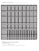
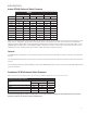
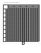
AIRFLOW DATA
Indoor CFM & External Static Pressure
Model
VHA09/VHA12 VHA18 VHA24
Fan Speed Low High Low High Low High
ESP (“) SCFM
0.0” 470
520 730 800 755 805
0.05” 460
510 670 735 700 750
0.10” 430
490 630 675 660 700
0.15” 410 470 595 640 615 665
0.20” 360 440 550 600 575 625
0.25”
310
400 505 550 525 580
0.30” 260 350 455 500 485 540
0.35” -- -- 400 445 450 500
0.40” -- -- 345 400 415 465
Indoor air ow may be determined by measuring the external static pressure (ESP) of the duct system using an inclined
manometer or magnahelic gauge and consulting the above chart to derive actual air ow. Under no circumstances
should the small chassis Vert-I-Pak equipment be operated at an external static pressure in excess of 0.3” W.C. on the
VHA09 & VHA12 and 0.4”W.C. on the VHA18 & VHA24. Operation of the Vert-I-Pak under these conditions will result in
inadequate air ow, leading to poor performance and/or premature component failure.
Control
For LOW speed only operation, connect the fan output terminal from the thermostat to the GL terminal of the electronic
control.
For HIGH speed only operation, connect the fan output terminal from the thermostat to the GH terminal of the electronic
control.
For thermostats with two-speed capability, connect the LOW speed output to the GL terminal and the HIGH speed output
to the GH terminal.
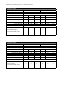
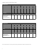
Condenser External Static Pressure
Model
Design Maximum
CFM
ESP ("WC) ESP ("WC)
VHA09 650 0.03 0.12
VHA12 650 0.03 0.12
VHA18 950 0.03 0.12
VHA24 980 0.03 0.12
Condenser CFM & External Static Pressure
VPAK is designed to install through an exterior wall with a plenum (VPAWP-8, VPAWP-14) and a Friedrich external louver .
If the Friedrich designed plenum and louver combinations are not used, the selections and design must be evaluated by Friedrich to ensure the
total pressure drop does not exceed the maximum allowable limits.