
Installation Instructions

4
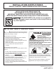
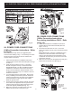
30” ELECTRIC FRONT CONTROL FREESTANDING INSTALLATION INSTRUCTIONS
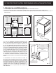
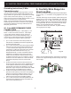
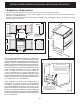
C. Level and Position Range - Level range by adjusting the
(4) leveling legs with a wrench. Note: Aminimum clearance
of 1/8” (3 mm) is required between the bottom of the
range and the leveling leg to allow room for the bracket.
Use a spirit level to check your adjustments. Slide range
back into position. Visually check that rear leveling leg
is inserted into and fully secured by the Anti-Tip Bracket
by removing lower panel or storage drawer. For models
with a warmer drawer or broiler compartment, grasp the
top rear edge of the range and carefully attempt to tilt it
forward.
4. Electrical Connection
Requirements
Avoid re hazard or electrical shock. Failure
to follow this warning may casue serious injury, re, or death.
This appliance must be properly installed and grounded
by a qualied technician in accordance with the National
Electrical Code ANSI/NFPA No. 70 -- latest edition -- and
Local Electrical Code requirements.
This appliance may be connected by means of “permanent
wiring” or power supply cord kit.”
When installing permanent wiring, do not leave excess
wire in range compartment. Excess wire in the range
compartment may not allow the rear access cover to be
replaced properly and could create a potential electrical
hazard if wires become pinched. Connect only as
instructed under “Permanent Wire Connections” in Step
5c. When using exible conduit or range cable use ex
connector or range cable strain relief
Models requiring power supply cord
kit
RISK OF FIRE OR ELECTRICAL SHOCK MAY OCCUR IF
AN INCORRECT SIZE RANGE CORD KIT IS USED, THE
INSTALLATION INSTRUCTIONS ARE NOT FOLLOWED
OR STRAIN RELIEF BRACKET IS DISCARDED.
This appliance may be connected by means of a power
supply cord. Only a power supply cord kit rated at 125/250
volts minimum, and marked for use with ranges shall be
used. See Fig. 10 for cord kit ampere rating information.
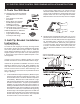
Cord must have either three (3) or four (4) conductors (See
Fig. 8). Terminals on end of wires must be either closed
loop or open-end spade lugs with upturned ends. Cord
must have strain relief properly installed. See Steps 5a. for
4-Wire or 4b. for 3-Wire connections.
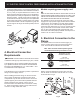
NOTE: Range is shipped from factory with 1-3/8" dia.
hole as shown. To use either 7/8" dia. hole or 1-1/8" dia.
knockouts refer to Fig. 9.
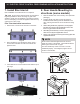
Fig. 8
3 & 4 - Wire electrical wall Receptacle types &
recommended mounting orientation on wall
Required for new and
remodeled installations
4-Wire Wall
receptacle (14-50R)
Allowed for
existing installations
3 Wire Wall
receptacle (10-50R)
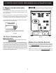
Fig. 9
Rear
Access
Cover
5. Electrical Connection to the
Range
The Rear Access Cover must be removed (Fig 9). To
remove, loosen center screw (one screw) and remove
cover. The terminal block will then be accessible.
Fig. 7
(17 mm)