
Installation Instructions

INSTRUCTION SHEET
©2021 Electrolux Home Products, Inc. Instruction Sheet A00343905 7.23.21
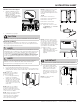
13. Use the clips provided to hold
the excess power cords to the
back of the units such that all
wires are away from the floor
(Fig. 13).
NOTE: Make sure the harnesses
and cables are cleared off the
floor before the units are pushed
back in place. This will prevent any
damage to the wires.
NOTE: The location of clips shown
is an example.
14. Plug the power supply into the
main outlet before pushing the
units into the final position.
Fig. 13
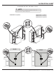
17. Attach the 1H top tie bar
(Fig. 16), keeping the 2 left
4H bolts loose.
Fig. 16
18. a. Open the doors and place the middle trim in between the
2 units.
b. Adjust the proximity
of the units as needed
to centralize the middle
trim. Start by fastening
the screws on top 1H
bracket in order to
evenly space the Center
Trim (Fig. 17).
Fig. 17
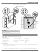
c. Fasten the four 8H screws (Fig. 14 and 15) through 2 front and
back 9H brackets. You may need several adjustments for the
center trim to be consistently flush and centered to the units.
NOTE Before continuing, ensure doors close without interference and
remain parallel. Adjusting the height of the wheels can help remedy door
alignment issues. Refer to INSTALLATION in the Use & Care Manual to
adjust the door height.
Fig. 18
NOTE
Some cabinet substrates may require pre-drilling holes using a
1
/
8
” (3
mm) diameter drill bit.
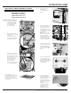
Electrolux TRMKTSS2LV84 Side Trim Attachment Setup
(some models)
19. Using eight 3H screws and
a power drill, attach the
two Side Trim Attachment
brackets to the front left and
right cabinet cut-out edges
with the brackets touching
the floor (Fig. 19). Ensure the
rectangular slots extend over
the cabinet edge.
Fig. 19
TRMKTEZ2FL75 (Frigidaire)
TRMKTEZ2LV79 (Frigidaire)
TRMKTEZ2FL79 (Frigidaire)
TRMKTSS2FL79 (Electrolux)
Side Trim Attachment Setup For:
20. Depending on which long
screw you received (6H or
7H), screw a long screw into
the lower left (Fig. 20A) of the
front wall cabinet, close to the
location shown in Fig. 20B.
21. Repeat step 20 for the right
side of the wall cabinet using
the other 6H/7H screw.
A
B
Fig. 20
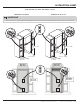
Trim Kit Tie Bar Installation
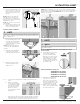
15. Having the refrigerator/
freezer standing side by side
½” apart, fasten a 9H bracket
to the front of the Levelers
(Fig. 14), keeping the left-side
8H screws loose.
NOTE: One side of the brackets
is slotted for fine adjustments in
step 18c.
Fig. 14
16. Attach the other 9H bracket
to the rear levelers (Fig. 15),
keeping the right screws loose.
Fig. 15
NOTE
Before proceeding with trim installation, make sure both refrigerator and
freezer are leveled front to back and side to side. Make sure all 8 wheels
are touching the floor.
NOTE
Before proceeding plug in units and verify they are functioning properly.