
Installation instructions


5
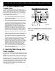
30” ELECTRIC FRONT CONTROL FREESTANDING INSTALLATION INSTRUCTIONS
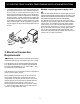
NOTE: Range is shipped from factory with 1-3/8" dia.
hole as shown. To use either 7/8" dia. hole or 1-1/8" dia.
knockouts refer to Fig. 9.
Fig. 8
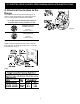
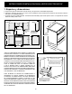
3 & 4 - Wire electrical wall Receptacle types &
recommended mounting orientation on wall
Required for new and
remodeled installations
4-Wire Wall
receptacle (14-50R)
Allowed for
existing installations
3 Wire Wall
receptacle (10-50R)
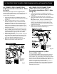
Fig. 9
Rear
Access
Cover
Fig. 11
4. Electrical Connection to the
Range
The Rear Access Cover must be removed (Fig 9). To
remove, loosen center screw (one screw) and remove
cover. The terminal block will then be accessible.