
Installation Instructions


10
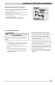
INSTALLATION REQUIREMENTS
NOTE
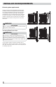
To achieve an installation with 0” (0 cm) clearance
for the back of the dryer (for other than straight back
venting), a quick-turn 90° dryer vent elbow must be
installed as described previously in this manual.
* Dryer must be vented straight back to achieve
0” (0 cm) rear installation.
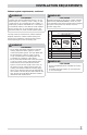
MINIMUM INSTALLATION CLEARANCES - Inches (cm)
SIDES REAR TOP FRONT
Alcove 0” (0 cm) 0” (0 cm)* 23” (58.5 cm) n/a
Closet 0” (0 cm) 0” (0 cm)* 23” (58.5 cm) 1” (2.5 cm)
1”
(2.5 cm)
0”
(0 cm)
23”
(58.5 cm)
Clearance requirements
IMPORTANT
DO NOT INSTALL YOUR DRYER:
1 In an area exposed to dripping water or outside
weather conditions.
2 In an area where it will come in contact with
curtains, drapes, or anything that will obstruct
the fl ow of combustion and ventilation air.
3 On carpet. Floor MUST be solid with a maximum
slope of 1 inch (2.54 cm).
0”
(0 cm)
0”
(0 cm)
WARNING
EXPLOSION HAZARD
Do not install the dryer where gasoline or other
fl ammables are kept or stored. If the dryer is installed
in a garage, it must be a minimum of 18 inches (45.7
cm) above the fl oor. Failure to do so can result in
death, explosion, fi re or burns.
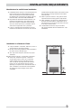
13.50”
(34.5 cm)
to center of rear vent
centerline height
for rear vent
27” (68.5 cm)
29” (73.5 cm)
to front of closed door
50” (127 cm)
to clear open door
fl oor line
1.6”
(4 cm)
3.75”
(9.5 cm)
3.7”
(9.5 cm)
42.5”
(108 cm)
38.5”
(98 cm)
gas supply
pipe on rear
of gas unit
electrical
supply on
rear of unit
1
Dryer Dimensions
1
Power supply cord length on gas unit approximately 60 inches (152.5 cm).