
Installation Instructions


3
INSTALLATION INSTRUCTIONS - FREESTANDING GAS RANGE
Fig. a
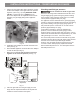
Tools you will need
(Wear safety glasses when using tools):
For leveling legs and Anti-Tip Bracket:
• Adjustable wrench or channel lock pliers (Fig. a)
• 5/16” Nutdriver or fl at head screwdriver (Fig. b)
• Electric drill & 1/8” drill bit (3/16” Masonry drill bit if
installing in concrete) (Fig. c)
• Level (Fig. d)
For gas supply connection:
• Adjustable wrench and pipe wrench (Figs. a & e)
For burner fl ame adjustment:
• Phillips head and small fl at-blade screwdrivers (Figs. f
& g)
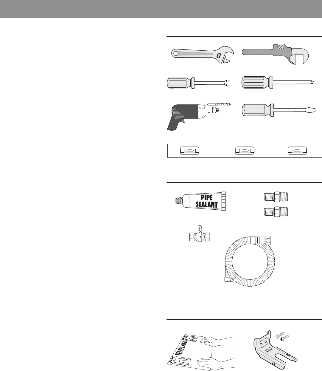
Materials you will need:
• Pipe joint sealant that resists action of LP/Propane gas
(Fig. h)
• Gas line manual shut-off valve (Fig. i)
• A new fl exible metal appliance conduit (1/2” NPT x
3/4” or 1/2” I.D.) must be design certifi ed by CSA
International. Because solid pipe restricts moving the
range, we recommend using a new fl exible conduit
(4 to 5 foot length) for each new installation and
additional reinstallations. (Fig. j)
• Use new fl are union adapters (1/2” NPT x 3/4” or 1/2”
I.D.) (Fig. k)
Materials supplied with appliance:
• Anti-Tip Template (Fig. l)
• Anti-Tip bracket; includes 2 mounting screws (Fig. m)
Tools
Fig. f
Materials
Fig. h
Fig. i
Fig. j
Fig. k
Fig. d
Fig. c
Fig. g
Fig. b
Fig. e
Fig. l
Fig. m
Materials supplied with appliance