
Use and Care Manual


2
C. Piping
1. Beforeinstalling,blow outpipe lineto removescaleand
other foreign matter.
2. ThisunithasDRYSEALpipethreads;usepipecompoundor
tapesparinglytomalethreadsonly.
3. Mounting(Grades11,9,7,5,3)-mountsothatinletand
outlet connections are horizontal (lter bowl vertical) to
ensureproperliquiddrainage.
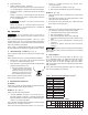
4. FlowDirection-installsothattheairowisinthedirection
of arrows on the filter head.
NOTE: Grade6ows fromoutside to insideof element.
Allother grades ow frominsideto outside of element.
Observeowarrowsoncap.
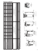
Figure1.2
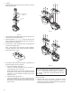
5. Directlter-to-lter(modular)connection-Filterheadsmay
bejoinedwithoutusingapipenipple
a. Bayonettypeheads(seeFigure1.3)
Use two (2) modular connectors, o-ring, and four (4)
socketheadcapscrews(soldaskit)
Removeblackplastictopcap,applygenerousamount
of lubricant to o-ring, install o-ring in groove, and insert
connectors. Screw connectors to head using socket
headcapscrews.
b. Threadedheads(seeFigure1.4)
Use four carriage bolts, nuts and o-ring (sold as kit).
Removeblackplastictopcaps,applygenerousamount
of lubricant to o-ring, install o-ring in groove, and install
bolts and nuts.
Wall Mounting
Bracket
Top Cap
Figure 1.1
Figure 1.3
Figure 1.4
NOTE:Makecertainowdirectionthroughltersiscorrect
(observepinholeusedforaligningtopcaps).Grades11,
9,7,5,3,1-whenholeisonsideclosesttoyou,inletisto
left.Grade6-whenholeisonthesidefartherfromyou,
inlet is to left.
NOTE: Lubricate o-ring with generous amount of lubricant
before installation.
6. Isolation valves and by-pass piping - For ease of service,
isolation and by-pass valves are desirable. In critical
applications,twoltersinstalledinparallelmaybenecessary
toavoidinterruptionofairsupply.