
Use and Care Manual


3
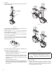
D. Drainprovisions
1. InternalAutomaticDrains-Drainline
Thebottomofinternalautomaticdrainsareprovidedwith
1/8"(insidethreads)forconnectionofadrainlineifdesired.
2. ExternalAutoDrains-Externalautodrainsmaybeadded
as follows:
Models12through28-removeinternaldrainandinstall
adapter(availablefromfactory).Adapteroutletconnection
is1/8"(insidethreads).
Discharge is at system pressure; anchor
drain line.
Models 32 through 48 - Remove adapter tting from
bottomofbowl;1/2"(insidethreads)portisavailablefor
externaldrainconnection.
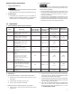
2.0 Operation
Do not operate filter at pressures in
excess of Maximum Working Pressureindicated on Serial
NumberTag.
NOTE:MaximumOperatingTemperature-150°F,66°C.Liquid
ltrationabove120°F,49°Cisnotrecommendedsincethereis
typicallyoilpresentinavaporstatewhichpassesthroughthe
filter and condenses downstream.
NOTE:Grade1-Ifoperatedabove100°F,38°Cmayexperience
lessthan1000hoursoflifebecauseofgreateroilvaporcontent.
A. Liquid Draining - Grades 11, 9, 7, 5, 3
NOTE: Collected liquids must be removed to ensure proper
operation.
NOTE:Depressurizeslowly,toavoidlterelementdamage.
1. ManualDrain-Turntoyourright(clockwise)toopenand
toyourleft(counterclockwise)toclose.
2. AutomaticDrain-Liquidswillautomaticallydischargewhen
sufficient accumulation occurs.
a. Internally Mounted Auto Drains
-These drains may be manually
drained by turning to your right
(clockwise)toopenandtoyour
left(counterclockwise)toclose.
NOTE:Manuallydraininternalautodrains
daily to verify drain function.
B. Operational Checkpoints
All Grades
Checkow,pressure,andtemperaturetomakecertainlter
isbeingoperatedwithindesignconditions.
Grades 11, 9, 7, 6, 5, 3
Checkpressuredropacrossthelter
1. Pressure differential in excess of 6 psi (0.42 kgf/cm
2
) -
pressureindicator in red area - indicates that the lter
sleeveorelementshouldbereplaced.Referencepage5,
Figure3.2forgaugescaledetail.
NOTE:Elementshouldbechangedannuallyorwhenindicator
changes to red, whichever occurs first.
NOTE:
Pressuredropshouldneverexceed15psi(1.0kgf/cm
2
).
OPEN ( TO RIGHT )
2. Check for sudden reduction in pressure drop.
Thismightindicate:
a. Possibleleakacrosselemento-ringseal
b. Leakthroughtheelementduetophysicaldamage
Grades 11, 9, 7, 5, 3
1. Checktoseethatlterisinstalledleveltoinsureproper
drainage.
2. Checkthatmanualdrainsaredrainedperiodicallyorthat
automatic drains are functioning.
3. OnmodelswithLiquidLevelSightglass-Checkthatliquid
levelisbelowtopofSightglass.
Grade 1
1. Checkforanoilysmellbyopeningthemanualvalve.Ifan
oilysmellexists,thefollowingshouldbechecked:
a. Filterelementadsorptioncapacityexhausted
b. Leakacrosselemento-ringseal
c. Leakthroughelementduetophysicaldamage
d. Presenceofliquidsbecauseoflackoforfailureofpre-
filters
e. Flow, pressure and temperatures outside design
conditions
f. Presence of gaseous impurities which cannot be
adsorbed
Methane,carbonmonoxide,carbondioxideand
various inorganic gases cannot be removed by an activated
carbon filter.
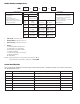
C. Flow Capacity
Maximum air ow for the various lters at 100 psig (7 kgf/
cm
2
)isindicatedinTable1.Todeterminemaximumairows
at inlet pressures other than 100 psig (7 kgf/cm
2
), multiply
owfromTable1byairowcorrectionfactorfromTable2
thatcorrespondstotheminimumoperatingpressureatthe
inlet of the filter.
NOTE:Filtersshouldnotbeselectedbypipesize.Selectusing
owrateandoperatingpressureonly.
Table 1 - Maximum Flow @100 psig [7 kgf/cm
2
]
Housing scfm [m
3
/hr]
CF12
20 [35]
CF16
35 [60]
CF20
60 [105]
CF24
100 [170]
CF28
170 [290]
CF32
250 [425]
CF36
375 [640]
CF40
485 [825]
CF44
625 [1060]
CF48
780 [1325]
Table 2 - Air Flow Correction Factor
Maximum
Inlet
Pressure
psig 20 30 40 60 80 100 120 150 200 250 300
kgf/cm
2
1.4 2.1 2.8 4.2 5.6 7.0 8.4 10.6 14.1 17.6 21.1
Correction Factor 0.30 0.39 0.48 0.65 0.82 1.00 1.17 1.43 1.87 2.31 2.74