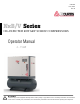
CAP-834 June, 2015 Rev. B NxB/V Series OIL-INJECTED ROTARY SCREW COMPRESSORS Operator Manual 4 – 15 kW WARNING Personal injury and/or equipment damage will be result by failing to pay attention to the vital safety information and instructions in this manual. Carefully read, understand, and retain all safety information and instructions before operating this compressor.
Limitation of liability Information on these operating instructions All information and instructions in this manual have been compiled taking account of the applicable standards and regulations, state-of-the-art technology and our years of knowledge and experience. These instructions enable you to use the machine safely and efficiently. The instructions are a component part of the machine and must be accessible for staff at all times.
Table of contents 1 Design and function ...............................................................................................................................7 1.1 Overview ........................................................................................................................................7 1.2 Brief description..............................................................................................................................9 1.3 Assembly description ...........
Table of contents 4.6 5 6 7 Installation and commissioning ......................................................................................................... 24 5.1 Safety instructions for the installation and commissioning .......................................................... 24 5.2 Requirements in the installation location ..................................................................................... 25 5.3 Installation ...........................................................
Table of contents 8.5 Commissioning after remedied fault.............................................................................................48 9 Index ......................................................................................................................................................49 10 Appendix ...............................................................................................................................................51 10.
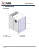
Design and function 1 Design and function 1.1 Overview Screw compressor Fig. 1: Standard screw compressor with belt drive 3 - 15 kW) 1 2 Controller Emergency stop button 3 4 Electrical cabinet Enclosure panels This chapter shows the screw compressors described in these instructions. They mainly differ in their construction, with or without receiver, and with the attachment of an additional section in which the refrigeration dryer and the frequency converter are installed.
Design and function Components The basic construction is the same for all screw compressor variants. The position or look of the assemblies may vary from the illustration Fig.
Design and function 1.2 Brief description 1.3.2 Enclosure panels The fresh air supplied by the cooling air fan is filtered through the intake filter. The air flows through the intake valve into the compressor airend, where it is compressed together with the injected oil to the final pressure. The oil is largely separated from the compressed air in the oil separator tank. The air/oil separator removes the remaining oil from the compressed air.
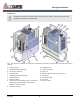
Design and function 1.3.5 Compressor airend Screw compressor withV-belt drive and frequency converter Fig. 7: Compressor airend The air is compressed by the compressor airend (Fig. 7/1) and fed to the oil separator tank (Fig. 7/2) together with the injected oil. The compressor airend and the oil separator tank are enclosed in the same housing. Fig.
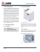
Design and function 1.3.6 Oil separator tank 1.3.7 Air/oil separator Fig. 10: Air/oil separator The air/oil separator (Fig. 10/1) removes the residual oil from the compressed air. Fig. 8: Oil separator tank 1 2 3 4 Oil separator Sight glass Filler nozzle Oil drain 1.3.8 Minimum pressure and non- return valve Fig. 11: Minimum pressure and non-return valve The minimum pressure and non-return valve (Fig. 11/1) does not open until the system pressure has risen to 72 psi (5 bar).
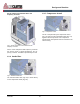
Design and function 1.3.9 Coolers 1.3.11 Cooling air fan Fig. 12: Coolers The compressed air is cooled in the air after-cooler (Fig. 12/1) before it leaves the screw compressor via the discharge port (Fig. 12/1). The oil is cooled by the oil cooler (Fig. 12/2) and fed back into the oil circuit. The plate (Fig. 12/3) can be removed for cleaning the coolers. Fig. 14: Screw compressor with air receiver (optional), refrigeration dryer (optional) and/or frequency converter 3–15 kWn 1.3.
Design and function 1.4 Interfaces 1.3.12 Refrigeration dryer Air supply Fig. 15: Refrigeration dryer The refrigeration dryer (Fig. 15/1) dries the compressed air using a heat exchange process. The compressed air is fed from the oil separator tank into the refrigeration dryer and then directed into the compressed air network via the compressed air port. Fig.
Safety 2 Safety This section is a summary of important safety aspects to ensure optimum protection of the personnel and safe and trouble-free operation. CAUTION! This combination of symbol and signal word indicates a possibly hazardous situation which may cause minor or light injuries if not avoided. The owner, lessor or operator of this compressor is hereby notified and forewarned that failure to observe these safety precautions may result in injury and/or property damage.
Safety 2.2 Proper use Warning – high-voltage. The machine is designed and constructed exclusively for the proper use described here. Warning – explosive substances. The screw compressor serves exclusively to generate compressed air in an environment not subject to explosion. The screw compressor must be supplied exclusively with cool, dry and dust-free cooling air. Warning – danger zone. Do not operate the compressor in excess of its rated pressures and speeds indicated on the compressor nameplate.
Safety 2.3 General safety 2.4 Safety devices 1. Read and understand all the instructions found in this manual before operating your compressor. 2. Disconnect the main power source before working on or performing any maintenance procedures on this unit. Use a lock out and tag out process. 3. Do not attempt to remove any parts, break any connection, loosen oil fill plug or drain plug until the unit has been shut down and air pressure has been relieved. 4.
Safety 2.4.2 Description of the installed Do not change the pressure setting of the pressure relief valve, restrict the function of the relief valve or replace the relief valve with a plug. safety devices Emergency stop button 2.5 Environmental protection NOTICE! Danger to the environment from incorrect handling of pollutants! Incorrect handling of pollutants, particularly incorrect waste disposal, may cause serious damage to the environment. Fig.
Safety 2.6 Instructions on the machine WARNING! Danger of symbols! injury from Hazardous Voltage illegible Stickers and signs can become dirty or otherwise obscured over time, with the result that dangers cannot be recognized and the necessary operating instructions cannot be complied with. This, in turn, poses a risk of injury. - All safety, warning and operating instructions must always be maintained in a completely legible condition. - Damaged signs or stickers must be replaced immediately.
Safety Brief instructions for operation This sticker is on the enclosure and contains brief instructions for operation.
Technical data 3 Technical data For more information refer to the technical data sheet. 3.1 Serial tag 1 2 3 4 5 6 Fig. 20: Serial tag The serial tag can be found on the enclosure. It includes the following details: 1. Manufacturer 2. Part number 3. Serial number 4. Motor power [HP] 5. Discharge pressure [PSI] 6.
Technical data 3.2 General specifications 3.2.1 Operating conditions Environment Data Value Temperature range +37 to +113F (+3 to +45°C) Relative humidity, maximum 60% Maximum installation altitude above sea level 3281ft (1000m) 3.2.2 Oil The following oils have been tested and approved for use in these compressors: Designation Type Synthetic oil FSC-8000 Food grade oil FSC-4000FG 3.2.
Transportation, packaging and storage 4 Transportation, packaging and storage 4.1 Safety instructions for 4.3 Packaging transportation About the packaging The individual screw compressors are packaged in cartons or sometimes on wooden frames and according to the anticipated transport conditions. Only environmentally-friendly materials are used for the packaging.
Transportation, packaging and storage Fragile 1. Drive the fork lift with the forks as shown in Fig. 21. 2. Insert the forks so that they stick out on the other side. Marks packages with fragile or sensitive contents. 3. Ensure that the package cannot tip if the centre of gravity if off-centre. Handle the package with care; do not allow to fall and do not expose to impacts. 4. Lift the package and begin transportation. 4.
Installation and commissioning 5 Installation and commissioning 5.1 Safety instructions for the there is a danger of serious injuries or death for persons in the danger zone. installation and commissioning - Electrical system DANGER! Danger to life from electric power! Contact with live parts may prove fatal. When switched on, electric components can be subject to uncontrolled movements and may cause grave injury or death.
Installation and commissioning 5.2 Requirements in the installation location Set up the screw compressor so that the following conditions are fulfilled: The installation location is level. The machine is easily accessible and can be accessed from all sides. There is sufficient lighting. There is sufficient ventilation. There is a power supply available. Escape paths and rescue equipment are freely accessible. Fig. 22: Shipping spacer The machine is not subjected to an explosive atmosphere.
Installation and commissioning NOTICE! Risk of material damage from condensation! Cooling air with moisture content can cause condensation. - Make sure that the cooling air is cool, dry and free of dust. 1. Provide the required rate of cooling air as per the technical data for the screw compressor ( Chapter 3 ‘Technical data’ on page 20). 2. Extract the exhaust air as per the technical data for the screw compressor ( Chapter 3 ‘Technical data’ on page 20).
Installation and commissioning 5.3.4 Connecting to the power supply the compressed air hose with high force. - Personnel: Qualified Electrician Anchor and fasten the compressed air hose sufficiently.
Installation and commissioning 5.4 Checking the oil level 1. Switch the screw compressor off and secure it to prevent it from being switched back on again. 2. Open and remove the enclosure panels with the special wrench. Fig. 26: Intake valve fastening screw 1 1. Unfasten the fastening screws on the intake valve (Fig. 26/1). Fig. 25: Inspection glass NOTICE! Property damage due to incorrect oil! 3. Check the inspection glass (Fig. 25/1) to make sure it is completely submerged in oil.
Installation and commissioning 5.6 Switching on after installation CAUTION! Danger of injury from oil vapor! 1. Check all connections to make sure they are installed correctly and all screws are properly fastened. In case of high temperatures oil vapor can form. Oil vapor can irritate eyes and the respiratory system. 2. Make sure that there are no tools or loose objects lying in or on the machine. - 3. Install the enclosure doors and make sure that they are sealed. 4.
Installation and commissioning 9. Check the compressor temperature Chapter 7.4.5 ‘Checking the compressor temperature’ on page 39. NOTICE! Risk of material damage due to too low or too high compressor temperature! 5.8 Setting parameters If the compressor temperature is too low or too high, the screw compressor may become damaged. - Refer to the controller documentation. For detailed information, contact the manufacturer.
Operation 6 Operation 6.1 Safety instructions for operation Improper operation WARNING! Danger of injury due to improper operation! Improper operation can cause serious injury and significant material damage. - Carry out all operating steps in accordance with the information and notices in this manual. - Pay attention to the following points before starting work: - - Ensure that all covers and safety devices are installed and work properly. - Ensure that that no one is in the danger zone.
Maintenance 7 Maintenance 7.1 Safety instructions for maintenance, there is a danger of serious injuries or death for persons in the danger zone. maintenance Electrical system - DANGER! Danger to life from electric power! Contact with live parts When switched components may be controlled movements grave injury. - may prove fatal.
Maintenance cloth or Kraft paper. - - components under pressure, make sure the pressure is relieved. Do not use flammable solvents for cleaning parts When reinstalling previously removed components, make sure that the components are mounted properly, all fixing elements are reinstalled, and all screws are tightened to torque. - Have faulty components that are under pressure during operation replaced by appropriate specialist personnel immediately.
Maintenance Environmental protection Observe the following environmental protection instructions during maintenance work: Loss of warranty The use of non-approved spare/replacement parts will invalidate the warranty. In respect of all lubrication points supplied manually with lubricant, remove any escaping, used or surplus grease and dispose of in accordance with applicable local, state and federal regulations. Procure replacement parts from authorized dealers or directly from the manufacturer.
Maintenance Nx (4-15kW) MAINTENANCE SCHEDULE* Oil sample Motor bearing lubrication Inspect antivibration pads Inspect drive coupling CAP-834 4 000 6 000 8 000 10 000 12 000 14 000 16 000 18 000 20 000 22 000 24 000 500 2 000 Check sump oil level (fill if necessary) Check pressure operating point and controls Check oil scavenger line for oil flow Drain condensate from air receiver Check pressure relief valve for 3 operation Drain condensate from sump Inspect/clean air suction filter element I
Maintenance 2000/ 6000 Hour Service Kit 4000 Hour Service Kit 8000 Hour Service Kit Change 2 Lubricant – Use CurtisLubePl us FSC-8000 24 000 22 000 20 000 18 000 16 000 14 000 12 000 10 000 8 000 6 000 4 000 2 000 500 QTY YRLY PART# WKLY. DESCRIPTION DLY. SERVICE INTERVALS (HOURS) FSK26NX4-6 FSK26NX8-15 1 FSK4NX4-6 FSK4NX8-15 FSK8NX4-6 FSK8NX15-6 1 1 5 US G 1 Notes: 1) Initial 500 h only. Follow regular intervals thereafter.
Maintenance 7.4 Maintenance work internal capacitors have been fully discharged. Necessary maintenance work Necessary maintenance work appears on the display of the controller as a warning Controller documentation. 1. Close the shut-off valve on the pressure network side and secure it to prevent it from being opened again. 2. Open and remove the enclosure panels with the special wrench. Observe all safety instructions and precautions as described in this manual, and in particular section 2.
Maintenance Topping up the oil Fig. 30: Filler pluge Fig. 29: Filler plug 5. Use a funnel (Fig. 30/1) to top up the oil to the filling edge on the filler plug (Fig. 30/3). 1. Close the shut-off valve on the pressure network side and secure it to prevent it from being opened again. 6. Position the gasket and check that it is firmly in place. 2. Open and remove the enclosure panels with the special wrench. 7. Insert the screw plug (Fig. 30/2) and tighten. 3.
Maintenance 1. Close the shut-off valve on the pressure network side and secure it to prevent it from being opened again. NOTICE! Property damage due to compressor temperature that is too low or too high! 2. Open and remove the enclosure panels with the special wrench. A compressor temperature that is too low or too high can cause damage to the screw compressor. 3. Use a drip pan to make sure that the leaking oil is collected. - For detailed information, contact the manufacturer.
Maintenance 7.4.7 Checking the drive unit 1. Close the shut-off valve on the pressure network side and secure it to prevent it from being opened again. 2. Open and remove the enclosure panels with the special wrench. 3. Visually check the drive unit. Fig. 33: Oil drain In case of visible defects, contact the manufacturer. 5. Open the oil drain (Fig. 33/2). The oil is drained. 7.4.8 Replacing the oil/changing the 6. Close the oil drain (Fig. 33/2).
Maintenance The oil is drained. 10. Switch on the compressor and switch it off again without waiting any longer than one minute controller documentation. 6. Close the oil drain (Fig. 36/1). 11. Check the oil level and top up as necessary Chapter 7.4.3 ‘Checking the oil level/topping up the oil’ on page 37. Replace the oil filter 1. Close the shut-off valve on the pressure network side and secure it to prevent it from being opened again. 2.
Maintenance 7.4.10 Replacing the intake filter Standard intake filter 1. Close the shut-off valve on the pressure network side and secure it to prevent it from being opened again. 2. Open and remove the enclosure panels with the special wrench. Fig. 38: Unfastening the air/oil separator 4. Use the strap wrench (Fig. 38/2) to unfasten and remove the air/oil separator (Fig. 38/1). 5. Remove old gasket remains from the air/oil separator. 6. Moisten the new gasket with a little oil. Fig.
Maintenance 7.5 Measures after maintenance shut-off valve. has been performed 4. Clean the work area and remove any substances such as liquids, processing material or similar that may have escaped. After completion of the maintenance work and before switching the machine on, carry out the following steps: 5. Ensure that all safety equipment on the machine functions perfectly. 1. Check whether all previously-removed protective equipment and covers have been replaced properly. 6.
Faults 8 Faults The following section describes possible causes of faults and the work to remedy them. Improperly executed troubleshooting work In case of faults that occur more than once, shorten the maintenance intervals according to the actual utilization. WARNING! Danger of injury from improper troubleshooting! In case of faults that cannot be remedied using the following instructions, contact the manufacturer.
Faults Oil vapor during all work hear hot surfaces. - Before all work, make sure that all surfaces have cooled off to the ambient temperature, wait at least 30 minutes. CAUTION! Danger of injury from oil vapor! In case of high temperatures oil vapor can form. Oil vapor can irritate eyes and the respiratory system.
Faults 8.3 Fault table Fault description Cause Remedy Compressor temperature too high Intake or ambient temperature too high Ventilate compressor room Cooling air intake or outlet blocked Unblock cooling air intake or outlet sufficiently Oil is soiled Change oil Chapter 7.4.8 ‘Replacing the oil/changing the oil filter’ on page 40 Oil low Top up oil Chapter 7.4.3 ‘Checking the oil level/topping up the oil’ on page 37 Oil cooler soiled Clean oil cooler Chapter 7.4.
Faults Fault description Cause Remedy Screw compressor does not start automatically or does not discharge after previous switchingoff by reaching the final pressure or from idle.
Faults 8.4 Work for fault clearance 6. Clean the return line (Fig. 41/1) and nozzle. If necessary, replace them with original spare parts ( Parts List). Clean/replace return line 1. Switch the screw compressor off and secure it to prevent it from being switched back on again. 7. Place the nozzle and return line (Fig. 41/1) back in position and tighten the screw connections. 2. Close the shut-off valve on the pressure network side and secure it to prevent it from being opened again. 8.
Index 9 Index A D Air/oil separator ......................................................11 Description of function .............................................9 Assemblies Drive unit ..................................................................9 Air/oil separator ..................................................11 Dryer ..................................................................... 13 Compressed air after-cooler ..............................12 E Compressor airend.................
Index Checking the oil level .........................................37 Relief valves .......................................................... 17 Oil change ..........................................................40 Replacing the intake filter ..................................... 42 Replacing the intake filter ...................................42 S Replacing the oil .................................................40 Safety ....................................................................
Appendix 10 Appendix 10.1 Bolt tightening torque requirements Lock screw/nuts B 158/193/196/251 design or similar Thread Category 8.8 Unit Category 10.9 Unit M5 3.69 (5) lbf ft (Nm) 7.38 (10) lbf ft (Nm) M6 5.9 (8) lbf ft (Nm) 13.28 (18) lbf ft (Nm) M8 14.75 (20) lbf ft (Nm) 32.45 (44) lbf ft (Nm) M 10 29.5 (40) lbf ft (Nm) 64.17 (87) lbf ft (Nm) M 12 50.89 (69) lbf ft (Nm) 111.37 (151) lbf ft (Nm) M 16 125.39 (170) lbf ft (Nm) 280.
Curtis-Toledo, Inc. 1905 Kienlen Avenue | St. Louis, Missouri 63133 www.fscurtis.com | info@fscurtis.