
Product Manual


Design and function
CAP-834
8
Components
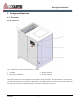
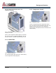
The basic construction is the same for all screw compressor variants. The position or look of the
assemblies may vary from the illustration
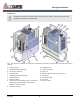
Fig. 2: Overview of the assemblies: Screw compressor with frequency converter, refrigeration dryer (optional) and air receiver
(optional)
1
Pressure gauge
2
Refrigeration dryer (optional)
3
Air receiver (optional)
4
Discharge port
5
Frequency converter (optional)
6
Air/oil separator
7
Electrical cabinet
8
Safety valve (second safety valve on tank for the
option with compressed air tank, positioned
behind the pressure gauge)
9
Compressor airend
10
Separator tank
11
Power connection
12
Drive unit
13
Minimum pressure and non-return valve
14
Intake filter
15
Thermostat valve
16
Oil cooler
17
Air after-cooler